b Maintenance and Service Guide Compaq Tablet PC TC1000 Document Part Number: 268627-001 November 2002 This guide is a troubleshooting reference used for maintaining and servicing the tablet PC. It provides comprehensive information on identifying tablet PC features, components, and spare parts, troubleshooting tablet PC problems, and performing tablet PC disassembly procedures.
© 2002 Compaq Information Technologies Group, L.P. Compaq and the Compaq logo are trademarks of Compaq Information Technologies Group, L.P. in the U.S. and/or other countries. Microsoft and Windows are trademarks of Microsoft Corporation in the U.S. and/or other countries. All other product names mentioned herein may be trademarks of their respective companies. Compaq shall not be liable for technical or editorial errors or omissions contained herein.
Contents 1 Product Description 1.1 Models . . . . . . . . . . . . . . . . . . . . . . . . . . . . . . . . . . . . 1–3 1.2 Features . . . . . . . . . . . . . . . . . . . . . . . . . . . . . . . . . . . 1–8 1.3 Clearing a Password. . . . . . . . . . . . . . . . . . . . . . . . . 1–10 1.4 Power Management . . . . . . . . . . . . . . . . . . . . . . . . . 1–11 1.5 Tablet PC External Components . . . . . . . . . . . . . . . 1–12 1.6 Keyboard Components. . . . . . . . . . . . . . . . . . . . . . . 1–24 1.
3 Illustrated Parts Catalog 3.1 Serial Number Location . . . . . . . . . . . . . . . . . . . . . . . 3–1 3.2 Tablet PC System Major Components. . . . . . . . . . . . 3–2 3.3 Miscellaneous Cable Kit Components . . . . . . . . . . . . 3–6 3.4 Miscellaneous Plastics/Hardware Kit Components . . 3–7 3.5 Keyboard . . . . . . . . . . . . . . . . . . . . . . . . . . . . . . . . . . 3–8 3.6 Docking Station . . . . . . . . . . . . . . . . . . . . . . . . . . . . . 3–9 3.7 Docking Station Components . . . . . . . . .
6 Specifications A Connector Pin Assignments B Power Cord Set Requirements 3-Conductor Power Cord Set . . . . . . . . . . . . . . . . . . . . . . General Requirements . . . . . . . . . . . . . . . . . . . . . . . . Country-Specific Requirements . . . . . . . . . . . . . . . . . . . . Notes . . . . . . . . . . . . . . . . . . . . . . . . . . . . . . . . . . . . .
vi Maintenance and Service Guide
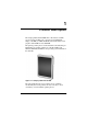
1 Product Description The Compaq Tablet PC TC1000 offers a Transmeta 1.0-GHz processor with 512-KB cache, a 10.4-inch color TFT XGA display, 256 MB (133 MHz) SDRAM, and nVidia GeForce2Go graphics with 16 MB of video SDRAM. The primary pointing device on the tablet PC is the tablet PC pen. Handwriting recognition software is available in Microsoft Windows XP Tablet PC Edition, the operating system installed on the tablet PC. Figure 1-1.
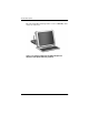
Product Description The optional docking station provides access to a MultiBay and a variety of connectors. Figure 1-2.
Product Description 1.1 Models Tablet PC models are shown in Tables 1-1 and 1-2 Table 1-1 Compaq Tablet PC TC1000 Naming Conventions Key CTC1000 T 100 X0 30 0 8 25 T XXXXXX-XXX 1 2 3 4 5 6 7 8 9 10 Key Description Options 1 Brand/Series designator C=Compaq 2 Processor type T=Transmeta 3 Processor speed 100=1.
Product Description Table 1-2 Compaq Tablet PC TC1000 Models The following Compaq Tablet PC TC1000 models use config. code LBSZ and feature: ■ Pen and PointStick keyboard ■ 6-cell, 4.
Product Description Table 1-2 Compaq Tablet PC TC1000 Models (Continued) The following Compaq Tablet PC TC1000 models use config. code LBRZ and feature: ■ Pen and PointStick keyboard ■ 6-cell, 4.
Product Description Table 1-2 Compaq Tablet PC TC1000 Models (Continued) The following models represent configure-to-order Compaq Tablet PC TC1000 models and use config. code LBQZ. These tablet PC models feature: ■ Pen and PointStick keyboard ■ 6-cell, 4.
Product Description Table 1-2 Compaq Tablet PC TC1000 Models (Continued) CTC1000 T 100 United States CTC1000 T 100 T 100 T 100 United States 76 T X0 30 0 8 38 T X0 30 0 8 25 T X0 30 0 C 76 T C 38 T C 25 T 470046-348 T 100 United States CTC1000 8 470046-340 United States CTC1000 0 470046-341 United States CTC1000 30 470046-342 United States CTC1000 X0 X0 30 0 470046-347 T 100 X0 30 0 470046-346 Maintenance and Service Guide 1–7
Product Description 1.2 Features 1–8 ■ 1.0-GHz Transmeta Crusoe 5800 processor with 512-KB integrated cache ■ nVidia GeForce2Go graphics controller with 16 MB SDRAM ■ 256 MB high-performance Synchronous DRAM (SDRAM), expandable to 768 MB ■ Microsoft Windows XP Tablet Edition ■ 10.4-inch XGA (1024 × 768) TFT display with over 16.7 million colors ■ Optional keyboard with PointStick pointing device ■ Internal combination Type III mini PCI 56Kbps, v.90/v.92 modem and wireless LAN 802.
Product Description ■ ❏ 8X Max DVD-ROM drive ❏ 8X Max DVD-CDRW combination drive ❏ 40- or 30-GB hard drive Support for the following connectors on the tablet PC: ❏ PC Card slot ❏ CompactFlash card slot ❏ ❏ RJ-45 network RJ-11 modem Universal Serial Bus External monitor AC power Stereo line out/headphone Mono microphone ❏ external MultiBay ❏ optional keyboard ❏ optional docking station ❏ ❏ ❏ ❏ ❏ ■ Support for the following connectors on the optional docking station: ❏ external MultiBa
Product Description 1.3 Clearing a Password If the tablet PC you are servicing has an unknown password, follow these steps to clear the password. These steps also clear CMOS: 1. Remove the battery pack and mini PCI communications/ memory expansion slot cover. Refer to Section 5.3, “Preparing the Tablet PC for Disassembly,” for more information. 2. Remove the RTC battery (refer to Section 5.4, “Real Time Clock (RTC) Battery”). 3. Wait approximately five minutes. 4.
Product Description 1.4 Power Management The tablet PC comes with power management features that extend battery operating time and conserve power.
Product Description 1.5 Tablet PC External Components The external components on the front panel of the tablet are shown in Figure 1-3 and described in Table 1-3. Figure 1-3. Front Panel Components Table 1-3 Front Panel Components Item Component Function 1 Wireless LAN activity light Off: The internal wireless LAN is off or not installed. On: The internal wireless LAN is on and connected to a network. Flashing: The internal wireless LAN is on, but is not connected to a network or properly configured.
Product Description Table 1-3 Front Panel Components (Continued) Item Component Function 2 Battery light On: A battery pack is charging. Flashing: A battery pack that is the only available power source has reached a low-battery condition. 3 AC adapter light On: AC power is being supplied through the AC adapter. 4 Journal launch button When the tablet PC is in Windows, opens and closes the Microsoft Journal application, which supports handwriting.
Product Description The tablet top side components are shown in Figure 1-4 and described in Table 1-4. Figure 1-4. Top Side Components Table 1-4 Top Side Components Item Component Function 1 USB connector Connects an optional USB 2.0- or 1.1-compliant device. 2 PC Card eject button Ejects an optional PC Card from the PC Card slot. 3 PC Card slot Supports an optional Type I or Type II 32-bit (CardBus) or 16-bit PC Card.
Product Description Table 1-4 Top Side Components (Continued) Item Component Function 7 CompactFlash card eject button Ejects an optional CompactFlash card from the CompactFlash card slot. 8 CompactFlash card slot Supports an optional Type I or Type II CompactFlash card. 9 External MultiBay connector Connects an optional USB 2.0- or 1.1-compliant device. 10 RJ-11 telephone jack Connects a modem cable. 11 RJ-45 network jack Connects an Ethernet network cable.
Product Description The tablet left side components are shown in Figure 1-5 and described in Table 1-5. Figure 1-5. Left Side Components Table 1-5 Left Side Components Item Component Function 1 Security cable slot Attaches an optional security cable to the tablet PC. 2 Screen protector slots (2) Secure the optional screen protector when it is attached to the tablet PC.
Product Description Table 1-5 Left Side Components (Continued) Item Component Function 3 Air vent Allows airflow to cool internal components. To prevent damage, the tablet PC shuts down if an Ä CAUTION: overheating condition occurs. Do not block the cooling vent. Avoid placing the tablet PC on a blanket, rug, or other flexible surface that may cover the vent area.
Product Description The tablet right side components are shown in Figure 1-6 and described in Table 1-6. Figure 1-6. Right Side Components Table 1-6 Right Side Components Item Component Function 1 Jog dial Functions like the enter and the up and down arrow keys on a standard keyboard. ■ Press inward to enter a command. ■ Rotate upward to scroll upward. ■ Rotate downward to scroll downward.
Product Description Table 1-6 Right Side Components (Continued) Item Component Function 3 Windows security button When pressed with the pen tip or a small object such as the end of a paper clip while: ■ Windows is open, enters the ctrl+alt+delete command. ■ The Setup utility is open, enters the reset command. 4 Tab button When the tablet PC is in Windows, functions like tab on a standard keyboard. 5 Q menu button When the tablet PC is in Windows, opens or closes the Q Menu.
Product Description The tablet bottom side components are shown in Figure 1-7 and described in Table 1-7. Figure 1-7. Bottom Side Components Table 1-7 Bottom Side Components Item Component Function 1 Docking alignment slots (2) Secure the tablet PC to an optional Tablet PC Docking Station. 2 Speakers (2) Produce stereo sound. 3 Audio line-out jack Connects optional stereo headphones or powered stereo speakers.
Product Description The components on the bottom of the tablet are shown in Figure 1-8 and described in Table 1-8. Figure 1-8. Bottom Components Table 1-8 Bottom Components Item Component Function 1 Tilt feet (2) While the tablet PC is being used in portrait orientation as a free-standing tablet, can elevate the top of the tablet PC to provide a comfortable writing and viewing angle.
Product Description Table 1-8 Bottom Components (Continued) Item Component Function 3 Product identification label Contains the serial number of the tablet PC and a code describing the original configuration of the tablet PC. You will need the serial number if you call Compaq customer support. 4 Docking connector Connects the tablet PC to an optional docking station. 5 Air vent Allows airflow to cool internal components.
Product Description Table 1-8 Bottom Components (Continued) Item Component Function 12 Battery quick check lights (3) On: Each light represents a percent of a full charge. For example, when all three lights are on, the battery pack is fully charged. Flashing: When one light is flashing, less than 10 percent of a full charge remains in the battery pack. 13 Battery quick check button Activates the battery quick check lights, which display how much charge remains in the battery pack.
Product Description 1.6 Keyboard Components The front panel components on the optional keyboard are shown in Figure 1-9 and described in Table 1-9. Figure 1-9. Keyboard Front Panel Components Table 1-9 Keyboard Front Panel Components Item Component Function 1 Alignment key Ensures the tablet PC is attached to the keyboard in the correct orientation. 2 Keyboard hooks (2) Secure the tablet PC to the keyboard.
Product Description Table 1-9 Keyboard Front Panel Components (Continued) Item Component Function 3 Keyboard connector Connects the keyboard to the keyboard connector on the tablet PC. 4 Tilt adjustment Tilts the tablet PC forward or backward while it is connected to the keyboard. 5 Rotation disk Rotates the tablet PC clockwise or counterclockwise while it is connected to the keyboard.
Product Description The external components on the front panel of the keyboard are shown in Figure 1-10 and described in Table 1-10. Figure 1-10.
Product Description Table 1-10 Keyboard Front Panel Components Item Component Function 1 Function keys Perform system and application tasks. For example, in the Microsoft Windows operating system and many applications, pressing F1 opens a Help file. To enter an F11 function, press the F11/F12 key. To enter an F12 function, press Fn+F11/F12. 2 Fn key Combines with other keys to perform system tasks. For example, pressing Fn+num lk turns on the keypad.
Product Description The components on the rear panel and bottom of the optional keyboard are shown in Figure 1-11 and described in Table 1-11. Figure 1-11.
Product Description Table 1-11 Keyboard Rear Panel and Bottom Components Item Component Function 1 Screen protector slots Attach the screen protector to the keyboard. 2 Attachment release switch Releases an attachment, such as the portfolio or optional screen protector, from the keyboard. 3 Universal alignment slots Secure the portfolio or optional screen protector to the keyboard. 4 Alignment key slot Accepts an alignment key to ensure proper orientation.
Product Description 1.7 Docking Station Components The front and left side components on the optional docking station are shown in Figure 1-12 and described in Table 1-12. Figure 1-12.
Product Description Table 1-12 Docking Station Front and Left Side Components Item Component Function 1 Docking stand Holds the tablet PC when it is docked. 2 Docking eject pin Disconnects the tablet PC and docking stand docking connectors when the release handle is pulled. 3 Release handle Ejects the tablet PC from the docking stand. 4 Docking connector Connects to the tablet PC. 5 Docking restraint latch Secures the tablet PC to the docking stand.
Product Description The rear panel and right side components on the optional docking station are shown in Figure 1-13 and described in Table 1-13. Figure 1-13.
Product Description Table 1-13 Docking Station Rear Panel and Right Side Components Item Component Function 1 Pivot arm Tilts the docking stand forward and backward to enable different viewing angles and different docking modes. 2 MultiBay Supports a diskette drive, CD-ROM or CD-RW drive, DVD drive, CD-RW/DVD drive, or second hard drive. 3 RJ-45 network jack Connects a network cable. 4 External monitor connector Connects an optional external monitor or overhead projector.
Product Description 1.8 Design Overview This section presents a design overview of key parts and features of the tablet PC. Refer to Chapter 3, “Illustrated Parts Catalog,” to identify replacement parts, and Chapter 5, “Removal and Replacement Procedures,” for disassembly steps.
2 Troubleshooting Å WARNING: Only authorized technicians trained by Compaq should repair this equipment. All troubleshooting and repair procedures are detailed to allow only subassembly/module level repair. Because of the complexity of the individual boards and subassemblies, no one should attempt to make repairs at the component level or to make modifications to any printed wiring board. Improper repairs can create a safety hazard.
Troubleshooting ■ Compaq Diagnostics—A system information and diagnostic utility that is used within your Windows operating system. Use this utility whenever possible to: ❏ Display system information. ❏ Test system components. ❏ Troubleshoot a device configuration problem in Windows 2000, Windows XP Professional, or Windows XP Home. is not necessary to configure a device connected to a USB ✎ Itconnector on the tablet PC or an optional docking base.
Troubleshooting Selecting from the File Menu Table 2-1 File Menu Select To Do This System Information ■ View identification information about the tablet PC, a docking base, and any battery packs in the system. ■ View specification information about the processor, memory and cache size, and system ROM. Save to Floppy Save system configuration settings to a diskette. Restore from Floppy Restore system configuration settings from a diskette.
Troubleshooting Selecting from the Security Menu Table 2-2 Security Menu Select To Do This Setup Password Enter, change, or delete a setup password. (The setup password is called an administrator password in Compaq Computer Security, a program accessed from the Windows Control Panel.) Power-on Password Enter, change, or delete a power-on password. DriveLock Passwords Enable/disable DriveLock; change a DriveLock User or Master password.
Troubleshooting Selecting from the Advanced Menu Table 2-3 Advanced Menu Select To Do This Language (or press F2) Change the Computer Setup language. Boot Options Enable/disable: Device Options ■ QuickBoot, which starts the tablet PC more quickly by eliminating some startup tests. (If you suspect a memory failure and want to test memory automatically during startup, disable QuickBoot.) ■ MultiBoot, which sets a startup sequence that can include most bootable devices and media in the system.
Troubleshooting Table 2-3 Advanced Menu (Continued) Select To Do This Device Options (continued) ■ Change the parallel port mode from EPP (Enhanced Parallel Port [default]) to standard, bidirectional, EPP or ECP (Enhanced Capabilities Port). ■ Set video-out mode to NTSC (default), PAL, NTSC-J, or PAL-M.* ■ Enable/disable all settings in the SpeedStep window. (When Disable is selected, the tablet PC runs in Battery Optimized mode.
Troubleshooting 2.2 Using Compaq Diagnostics When you access Compaq Diagnostics, a scan of all system components is displayed on the screen before the Compaq Diagnostics window opens. You can display more or less information from anywhere within Compaq Diagnostics by selecting Level on the menu bar. Compaq Diagnostics is designed to test Compaq components. If non-Compaq components are tested, the results may be inconclusive. Obtaining, Saving, or Printing Configuration Information 1.
Troubleshooting Obtaining, Saving, or Printing Diagnostic Test Information 1. Access Compaq Diagnostics by selecting Start > Settings > Control Panel > Compaq Diagnostics. 2. Select the Test tab. 3. In the scroll box, select the category or device you want to test. 4. Select a test type: 2–8 ❏ Quick Test—Runs a quick, general test on each device in a selected category. ❏ Complete Test—Performs maximum testing on each device in a selected category.
Troubleshooting 5. Select a test mode: ❏ Interactive Mode—Provides maximum control over the testing process. You determine whether the test was passed or failed and may be prompted to insert or remove devices. ❏ Unattended Mode—Does not display prompts. If errors are found, they are displayed when testing is complete. 6. Select the Begin Testing button. 7. Select a tab to view a test report: ❏ Status tab—Summarizes the tests run, passed, and failed during the current testing session.
Troubleshooting 2.3 Troubleshooting Flowcharts Table 2-4 Troubleshooting Flowcharts Overview Flowchart Description 2.1 Initial troubleshooting 2.2 No power, part 1 2.3 No power, part 2 2.4 No power, part 3 2.5 No power, part 4 2.6 No video, part 1 2.7 No video, part 2 2.8 Nonfunctioning docking station 2.9 No operating system (OS) loading 2.10 No OS loading from hard drive, part 1 2.11 No OS loading from hard drive, part 2 2.12 No OS loading from hard drive, part 3 2.
Troubleshooting Flowchart 2.1—Initial Troubleshooting Begin troubleshooting. N Go to Section 2.2, No Power. Is there power? Y N Check LED board, speaker connections. Beeps, LEDs, or error messages? N Y Go to Section 2.17, Nonfunctioning Device. All drives working? N Y Go to Section 2.6, No Video. Is there video? (no boot) N Keyboard/ pointing device working? Y N Y Go to Section 2.9, No OS Loading. Is the OS loading? N Connecting to network or modem? Y N Is there sound? Go to Section 2.
Troubleshooting Flowchart 2.2—No Power, Part 1 No Power (power LED is off). Remove from docking station (if applicable). N N Power up on battery power? Go to Section 2.3, No Power, Part 2. Power up on battery power? *Reset power. Y Y N N Power up on AC power? Power up on AC power? *Reset power. Y Go to Section 2.4, No Power, Part 3. Y Y Power up in docking station? Done N 1. Reseat the power cables in the docking station and at the AC outlet. 2. Ensure the AC power source is active. 3.
Troubleshooting Flowchart 2.3—No Power, Part 2 Continued from Section 2.2, No Power, Part 1. Visually check for debris in battery socket and clean if necessary. Y Power on? Done N Check battery by recharging, moving it to another tablet PC, or replacing it. N Replace power supply (if applicable). Power on? Y N Done Power on? Go to Section 2.4, No Power, Part 3.
Troubleshooting Flowchart 2.4—No Power, Part 3 Continued from Section 2.3, No Power, Part 2. Plug directly into AC outlet. Y Power LED on? Done N Reseat AC adapter in tablet PC and at power source. Y Power on? Done N N Power outlet active? External Try different outlet. Y Internal or external AC adapter? N Internal Go to Section 2.5, No Power, Part 4. Replace power cord. Power on? Y Y Power on? Replace external AC adapter.
Troubleshooting Flowchart 2.5—No Power, Part 4 Continued from Section 2.4, No Power, Part 3. Open tablet PC. Y Loose or damaged parts? N Reseat loose components and boards and replace damaged items. Close tablet PC and retest. N Power on? Replace the following items (if applicable). Check tablet PC operation after each replacement: 1. Internal DC-DC converter* 2. Internal AC adapter 3. Processor board* 4.
Troubleshooting Flowchart 2.6—No Video, Part 1 No Video. Docking Station Go to Section 2.7, No Video, Part 2. Stand-alone or Docking Station? *NOTE: To change from internal to external display, use the hotkey combination. Stand-alone Internal or external display*? Y Adjust brightness. Press lid switch to ensure operation. A Adjust brightness. Y Video OK? Done N Internal External Video OK? Y Video OK? Done N Done N Replace the following one at a time. Test after each replacement. 1.
Troubleshooting Flowchart 2.7—No Video, Part 2 Continued from Section 2.6, No Video, Part 1. Remove tablet PC from docking station, if connected. Adjust display brightness. Check brightness of external monitor. N Y Go to “A” in Section 2.6, No Video, Part 1. Video OK? Y Video OK? Done N Check that tablet PC is properly seated in docking station, for bent pins on cable, and for monitor connection. Try another external monitor.
Troubleshooting Flowchart 2.8—Nonfunctioning Docking Station (if applicable) Nonfunctioning Docking Station. Reseat power cord in docking station and power outlet. Reinstall tablet PC into docking station. Check voltage setting on docking station. Y Reset monitor cable connector at docking station. Docking station operating? Done N Y Docking station operating? N Remove tablet PC, reseat all internal parts, and replace any damaged items in docking station.
Troubleshooting Flowchart 2.9—No Operating System (OS) Loading No OS Loading.* Reseat power cord in docking station and power outlet. No OS loading from hard drive, go to Section 2.10. No OS loading from diskette drive, go to Section 2.13. No OS loading from CD- or DVD-ROM drive, go to Section 2.14. No OS loading from network, go to Section 2.20. *NOTE: Before beginning troubleshooting, always check cable connections, cable ends, and drives for bent or damaged pins.
Troubleshooting Flowchart 2.10—No OS Loading from Hard Drive, Part 1 OS not loading from hard drive. Y Nonsystem disk message? N Go to Section 2.11, No OS Loading from Hard Drive, Part 2. Reseat external hard drive. Y OS loading? Done N N Boot from CD? N Y Boot from diskette? Check the setup utility for correct booting order. Y N Go to Section 2.13, No OS Loading from Diskette Drive. Change boot priority through the setup utility and reboot.
Troubleshooting Flowchart 2.11—No OS Loading from Hard Drive, Part 2 Continued from Section 2.10, No OS Loading from Hard Drive, Part 1. Reseat hard drive. N 1. Replace hard drive. 2. Replace system board. CD or diskette in drive? Y Hard drive accessible? Y Done N Remove diskette and reboot. Run FDISK. Y Boot from hard drive? N Done N Create partition, then format hard drive to bootable C:\ prompt. Hard drive partitioned? Y N Boot from diskette drive? Y N Go to Section 2.
Troubleshooting Flowchart 2.12—No OS Loading from Hard Drive, Part 3 Continued from Section 2.11, No OS Loading from Hard Drive, Part 2. N System files on hard drive? Install OS and reboot. Y Y Y Virus on hard drive? OS loading from hard drive? Clean virus. N Done N Y Run SCANDISK and check for bad sectors. Diagnostics on diskette? Replace hard drive. N N Can bad sectors be fixed? Run diagnostics and follow recommendations. Replace hard drive. Y N Fix bad sectors.
Troubleshooting Flowchart 2.13—No OS Loading from Diskette Drive Y OS not loading from diskette drive. Reseat diskette drive. OS loading? Done N Y N Bootable diskette in drive? Nonsystem disk message? N Install bootable diskette and reboot tablet PC. Y N Check diskette for system files. Try different diskette. Go to Section 2.17, Nonfunctioning Device. Boot from another device? Y Y N Diskette drive enabled in the setup utility? Enable drive and cold boot tablet PC. Y 1.
Troubleshooting Flowchart 2.14—No OS Loading from CD- or DVD-ROM Drive Y No OS Loading from CD- or DVD-ROM Drive. N Bootable disc in drive? Disc in drive? N Y Install bootable disc and reboot tablet PC. Try another bootable disc. Install bootable disc. Y Boots from CD or DVD? Done N Y Reseat drive. Boots from CD or DVD? Done N N Booting from another device? Y Y Booting order correct? N Go to Section 2.17, Nonfunctioning Device. Clear CMOS. Refer to Section 1.
Troubleshooting Flowchart 2.15—No Audio, Part 1 Y Turn up audio internally or externally. No Audio. Audio? Done N N Y Tablet PC in docking station (if applicable)? N Go to Section 2.16, No Audio, Part 2. Internal audio? Undock Y Replace the following docking station components one at a time as applicable. Check after each change. Go to Section 2.16, No Audio, Part 2. 1. Reseat docking station audio cable. 2. Replace audio cable. 3. Replace speaker. 4. Replace docking station audio board. 5.
Troubleshooting Flowchart 2.16—No Audio, Part 2 Continued from Section 2.15, No Audio, Part 1. N Audio driver in OS configured? Reload audio drivers. Y N Correct drivers for application? Load drivers and set configuration in OS. Y Connect to external speaker. N Audio? Y Replace audio board and speaker connections in tablet PC (if applicable). Y Audio? Done N 1. Replace internal speakers. 2. Replace audio board (if applicable). 3. Replace system board.
Troubleshooting Flowchart 2.17—Nonfunctioning Device Nonfunctioning Device. Reseat device. Unplug the nonfunctioning device from the tablet PC, and inspect cables and plugs for bent or broken pins or other damage. Y Clear CMOS. Any physical device detected? Fix or replace broken item. Possible bad hard drive. Replace drive. Go to Section 2.9, No OS Loading. N Reattach device. Close tablet PC, plug in power, and reboot.
Troubleshooting Flowchart 2.18—Nonfunctioning Keyboard Keyboard not operating properly. Connect tablet PC to good external keyboard. N Replace system board. External device works? Y Reseat internal keyboard connector (if applicable). N Replace internal keyboard or cable. OK? Y Y OK? Done Done N Replace system board.
Troubleshooting Flowchart 2.19—Nonfunctioning Pointing Device Pointing device not operating properly. Connect tablet PC to good external pointing device. N External device works? Replace system board. Y Reseat internal pointing device connector (if applicable). N Replace internal pointing device or cable. OK? Y Y Done OK? Done N Replace system board.
Troubleshooting Flowchart 2.20—No Network or Modem Connection No network or modem connection. N Network or modem jack active? Replace jack or have jack activated. Y Y Connect to nondigital line. Digital line? N N NIC/modem configured in OS? Y Reload drivers and reconfigure. OK? Done N Y Disconnect all power from the tablet PC and open. Replace NIC/modem (if applicable). Y Reseat NIC/modem (if applicable). OK? Done N Replace system board.
3 Illustrated Parts Catalog This chapter provides an illustrated parts breakdown and a reference for spare part numbers and option part numbers. 3.1 Serial Number Location When ordering parts or requesting information, provide the tablet PC serial number and model number located on the bottom of the tablet PC (Figure 3-1). Figure 3-1.
Illustrated Parts Catalog 3.2 Tablet PC System Major Components Figure 3-2.
Illustrated Parts Catalog Table 3-1 Spare Parts: Tablet PC System Major Components Item Description 1 Display components Display panel assembly Display bezel with inverter Bridge battery Digitizer Miscellaneous Cable Kit, includes: 2a 2b 2c 2d 2e 3g 311062-001 310667-001 310676-001 310666-001 310673-001 Switch board cable Digitizer cable Speaker cable Display panel cable Modem cable not illustrated: display inverter cable Miscellaneous Plastic/Hardware Kit, includes: 3a 3b 3c 3d 3e 3f Spare Part
Illustrated Parts Catalog Figure 3-2.
Illustrated Parts Catalog Table 3-1 Spare Parts: Tablet PC System Major Components (Continued) Spare Part Number Item Description 4 System board (includes fan, heat sink, and 256 MB memory) Fan and heat sink (not illustrated separately) 310664-001 5 Switch board 310672-001 6 Base enclosure (includes battery shield, hard drive bracket, LED board assembly, connector cover, and shields) 310671-001 7 Speaker assembly (includes audio board) 310679-001 8 Wireless local area network (LAN) board (m
Illustrated Parts Catalog 3.3 Miscellaneous Cable Kit Components Figure 3-3.
Illustrated Parts Catalog 3.4 Miscellaneous Plastics/Hardware Kit Components Figure 3-4.
Illustrated Parts Catalog 3.5 Keyboard Figure 3-5.
Illustrated Parts Catalog 3.6 Docking Station Figure 3-6.
Illustrated Parts Catalog 3.7 Docking Station Components Figure 3-7.
Illustrated Parts Catalog Table 3-6 Docking Station Components Item Description Spare Part Number 1 Docking stand and pivot arm 311189-001 2 Top case 311190-001 3 Board assembly 311192-001 4 Bottom case 311191-001 Maintenance and Service Guide 3–11
Illustrated Parts Catalog 3.8 Miscellaneous Table 3-7 Spare Parts: Miscellaneous (not illustrated) Spare Part Number Description AC power cord, 3 wire Australia Europe International Italy Japan Korea People’s Republic of China 198723-011 198723-B31 198723-061 198723-291 198723-AD1 198723-AA1 Sweden Switzerland Taiwan United Kingdom United States 198723-101 198723-BG1 198723-AB1 198723-031 198723-001 AC adapter, 65 W 285288-001 Pen (uses a 1.
4 Removal and Replacement Preliminaries This chapter provides essential information for proper and safe removal and replacement service. 4.
Removal and Replacement Preliminaries 4.2 Service Considerations The following sections include some of the considerations that you should keep in mind during disassembly and assembly procedures. you remove each subassembly from the tablet PC, place the ✎ As subassembly (and all accompanying screws) away from the work area to prevent damage. Plastic Parts Using excessive force during disassembly and reassembly can damage plastic parts. Use care when handling the plastic parts.
Removal and Replacement Preliminaries 4.3 Preventing Damage to Removable Drives Removable drives are fragile components that must be handled with care. To prevent damage to the tablet PC, damage to a removable drive, or loss of information, observe the following precautions: ■ Before removing or inserting a hard drive, shut down the tablet PC. If you are unsure whether the tablet PC is off or in Hibernation, turn on the tablet PC, then shut it down.
Removal and Replacement Preliminaries 4.4 Preventing Electrostatic Damage Many electronic components are sensitive to electrostatic discharge (ESD). Circuitry design and structure determine the degree of sensitivity. Networks built into many integrated circuits provide some protection, but in many cases the discharge contains enough power to alter device parameters or melt silicon junctions.
Removal and Replacement Preliminaries ■ Store reusable electrostatic-sensitive parts from assemblies in protective packaging or nonconductive foam. ■ Use transporters and conveyors made of antistatic belts and roller bushings. Ensure that mechanized equipment used for moving materials is wired to ground and that proper materials are selected to avoid static charging. When grounding is not possible, use an ionizer to dissipate electric charges. 4.
Removal and Replacement Preliminaries 4.7 Grounding Equipment and Methods Grounding equipment must include either a wrist strap or a foot strap at a grounded workstation. ■ When seated, wear a wrist strap connected to a grounded system. Wrist straps are flexible straps with a minimum of one megohm ±10% resistance in the ground cords. To provide proper ground, wear a strap snugly against the skin at all times. On grounded mats with banana-plug connectors, connect a wrist strap with alligator clips.
Removal and Replacement Preliminaries ■ Nonconductive plastic bags, tubes, or boxes ■ Metal tote boxes ■ Electrostatic voltage levels and protective materials Table 4-1 shows how humidity affects the electrostatic voltage levels generated by different activities.
Removal and Replacement Preliminaries 4–8 Maintenance and Service Guide
5 Removal and Replacement Procedures This chapter provides removal and replacement procedures. Torx T8 and Phillips P0 screws are removed during the disassembly of the tablet PC and the docking station. There are 36 screws, in 4 different sizes, that must be removed, replaced, and loosened when servicing the tablet PC. There are 17 screws, in 4 different sizes, that must be removed and replaced when servicing the docking station.
Removal and Replacement Procedures 5.1 Serial Number Report the tablet PC serial number to Compaq when requesting information or ordering spare parts. The serial number is located on the bottom of the tablet PC (Figure 5-1). Figure 5-1.
Removal and Replacement Procedures 5.2 Disassembly Sequence Chart Use the chart below to determine the section number to be referenced when removing tablet PC components. Table 5-1 Disassembly Sequence Chart Section Description 5.3 Preparing the tablet PC for disassembly Number of screws removed Battery pack 1 Mini PCI communications board 2 Memory expansion board 0 Hard drive 2 5.4 Real time clock (RTC) battery 0 5.5 Display panel assembly 16 5.6 Speaker assembly 0 5.
Removal and Replacement Procedures 5.3 Preparing the Tablet PC for Disassembly Perform the following steps before disassembling the tablet PC: 1. Turn off the tablet PC. 2. Disconnect the AC adapter and all external devices. 3. Remove the battery pack by following these steps: Battery Pack Spare Part Number Information Battery pack, Li ion 302119-001 a. Turn the tablet panel side down with the power switch and jog dial facing you.
Removal and Replacement Procedures b. Remove the PM2.0 × 4.0 screw 1 that secures the battery pack to the tablet PC (Figure 5-2). c. Slide the battery release latch 2 toward the back of the tablet to release the battery pack. d. Use the notch in the battery pack to lift the left side of the battery pack up and swing it to the right 3. e. Remove the battery pack. Figure 5-2. Removing the Battery Pack Reverse the preceding procedures to install the battery pack.
Removal and Replacement Procedures 4. Remove the mini PCI communications board by following these steps: a. Turn the tablet panel side down with the power switch and jog dial facing you. b. Remove the two PM2.0 × 4.0 screws 1 that secure the mini PCI communications/memory expansion slot cover to the tablet PC (Figure 5-3). c. Lift the back edge of the mini PCI communications/ memory expansion slot cover up and swing it forward 2. d. Remove the mini PCI communications/memory expansion slot cover.
Removal and Replacement Procedures e. Disconnect the modem cable 1 and the two antenna cables 2 from the mini PCI communications board (Figure 5-4). f. Spread the retaining tabs 3 securing the mini PCI communications board to the system board. g. The mini PCI communications board will rise up at a 45-degree angle. h. Pull the mini PCI communications board away from the connector at a 45-degree angle 4. Figure 5-4.
Removal and Replacement Procedures 5. Remove the memory expansion board by following these steps: a. Remove the mini PCI communications/memory expansion slot cover. b. Spread the retaining tabs 1 securing the memory expansion board to the system board (Figure 5-5). c. The memory expansion board will rise up at a 45-degree angle. d. Pull the memory expansion board away from the connector at a 45-degree angle 2. Figure 5-5.
Removal and Replacement Procedures 6. Remove the hard drive by following these steps: a. Turn the tablet PC panel side down with the power switch and jog dial facing you. b. Remove the two PM2.0 × 4.0 screws 1 that secure the hard drive cover to the tablet PC (Figure 5-6). c. Lift the front edge of the cover up and swing the cover back 2. d. Remove the hard drive cover. hard drive cover is included in the Miscellaneous ✎ The Plastics/Hardware kit, spare part number 310678-001. Figure 5-6.
Removal and Replacement Procedures e. Use the tab 1 on the right side of the hard drive to slide the drive to the right 2 and disconnect it from the system board (Figure 5-7). f. Remove the hard drive from the tablet 3. Figure 5-7. Removing the Hard Drive Reverse the preceding procedures to install the hard drive.
Removal and Replacement Procedures 5.4 Real Time Clock (RTC) Battery RTC Battery Spare Part Number Information Disk cell RTC battery 310675-001 Perform the following steps to remove the RTC battery: 1. Prepare the tablet PC for disassembly (Section 5.3). 2. Remove the mini PCI communications/memory expansion slot cover. 3. Turn the tablet PC panel side down with the power switch and jog dial facing you. 4. Disconnect the RTC battery cable from the system board 1 (Figure 5-8). 5.
Removal and Replacement Procedures 5.5 Display Panel Assembly Display Panel Assembly Components Spare Part Number Information Display panel assembly Display bezel with inverter Bridge battery Digitizer 311062-001 310667-001 310676-001 310666-001 Perform the following steps to remove and disassemble the display panel assembly: 1. Prepare the tablet PC for disassembly (Section 5.3). 2. Turn the tablet PC panel side down with the power switch and jog dial facing you.
Removal and Replacement Procedures 3. Remove the seven TM2.5 × 7.0 screws 1 that secure the display panel assembly to the tablet PC (Figure 5-9). 4. Open the bottom tilt foot 2 and remove the TM2.5 × 7.0 screw 3 that secures the display panel assembly to the tablet PC. Figure 5-9.
Removal and Replacement Procedures 5. Slide and hold the keyboard release latch 1 to the right (Figure 5-10). 6. Remove the TM2.5 × 7.0 screw 2 that secures the display panel assembly to the tablet PC. 7. Disconnect the digitizer cable 3 in the hard drive bay. Figure 5-10.
Removal and Replacement Procedures 8. Turn the tablet PC panel side up with the power switch and jog dial facing you. 9. Lift and hold the front edge of the base enclosure 1 until it rests at a 45-degree angle (Figure 5-11). 10. Release the ZIF connector 2 to which the inverter cable is attached and disconnect the cable 3. 11. Lift the base enclosure straight up 4 to remove it from the display panel assembly. Figure 5-11.
Removal and Replacement Procedures 12. Position the display panel assembly so the display panel is facing down and the inverter and bridge battery are facing you. 13. Remove the two PM2.0 × 5.0 screws 1 that secure the display panel bracket to the display panel assembly (Figure 5-12). 14. Remove the display panel bracket 2. Figure 5-12.
Removal and Replacement Procedures 15. Disconnect the inverter board cable 1 from the inverter board (Figure 5-13). 16. Release the ZIF connector 2 to which the inverter board cable is attached and disconnect the cable 3. 17. Remove the tape 4 that secures the inverter board cable to the back of the display panel. Figure 5-13.
Removal and Replacement Procedures 18. Remove the four PM2.0 × 4.0 screws 1 that secure the display panel to the display bezel (Figure 5-14). 19. Swing the two flex cables to the left 2. 20. Lift the front edge of the display panel 3 and slide it forward 4 to remove it from the display bezel. Figure 5-14.
Removal and Replacement Procedures 21. Remove the PM2.0 × 5.0 screw 1 that secures the digitizer to the display panel assembly (Figure 5-15). 22. Lift the front edge of the digitizer 2 and slide it out 3 of the display panel. Figure 5-15.
Removal and Replacement Procedures 23. Disconnect the bridge battery cable 1 from the panel inverter board (Figure 5-16). 24. Remove the bridge battery 2 from the panel bezel. Figure 5-16. Removing the Bridge Battery Reverse the preceding procedures to reassemble and install the display panel assembly.
Removal and Replacement Procedures 5.6 Speaker Assembly Speaker Assembly Spare Part Number Information Speaker assembly and audio board 310679-001 Perform the following steps to remove the speaker assembly: 1. Prepare the tablet PC for disassembly (Section 5.3). 2. Remove the display panel assembly (Section 5.5). 3. Turn the tablet PC base enclosure top side up with the power switch and jog dial facing you. 4.
Removal and Replacement Procedures 6. Release the system board ZIF connector 1 to which the speaker cable is attached and disconnect the cable 2 from the system board (Figure 5-18). 7. Remove the tape 3 that secures the speaker cable to the PC Card assembly. 8. Remove the speaker cable 4. speaker cable is included in the Miscellaneous Cable Kit, ✎ The spare part number 310673-001. Figure 5-18. Removing the Speaker Cable Reverse the preceding procedures to install the speaker assembly.
Removal and Replacement Procedures 5.7 Digitizer Cable digitizer cable is included in the Miscellaneous Cable Kit, ✎ The spare part number 310673-001. Perform the following steps to remove the digitizer cable: 1. Prepare the tablet PC for disassembly (Section 5.3). 2. Remove the display panel assembly (Section 5.5). 3. Disconnect the digitizer cable 1 from the system board (Figure 5-19). 4. Remove the digitizer cable from the clips in the heat sink 2. 5.
Removal and Replacement Procedures 5.8 System Board System Board Spare Part Number Information System board with fan and heat sink (includes 256 MB memory) 310664-001 Perform the following steps to remove the system board: 1. Prepare the tablet PC for disassembly (Section 5.3). 2. Remove the display panel assembly (Section 5.5).
Removal and Replacement Procedures 3. Position the tablet PC base enclosure so the heat sink grille faces you. 4. Remove the four TM2.5 × 7.0 screws 1 that secure the keyboard release assembly to the base enclosure (Figure 5-20). 5. Lift the keyboard release assembly straight up 2 and remove it from the base enclosure. keyboard release assembly is included in the Miscellaneous ✎ The Plastics/Hardware kit, 310678-001. Figure 5-20.
Removal and Replacement Procedures installing the keyboard release assembly, make sure the ✎ When actuator tab 1 in the base enclosure is in the leftmost position. After this tab is positioned properly, install the keyboard release assembly 2 and screws 3 (Figure 5-21). Figure 5-21.
Removal and Replacement Procedures 6. Position the base enclosure so the PC Card slot is facing you. 7. Press the PC Card release button 1 to release it from the base enclosure. Press the button a second time to eject the contents of the PC Card slot (Figure 5-22). 8. Remove the PC Card slot device 2 from the PC Card slot. 9. Press the CompactFlash card release button 3 to release it from the base enclosure. Press the button a second time to eject the contents of the CompactFlash card slot. 10.
Removal and Replacement Procedures 11. Release the ZIF connector 1 to which the switch board cable is attached and disconnect the cable 2 from the system board (Figure 5-23). 12. Release the ZIF connector 3 to which the switch board cable is attached and disconnect the cable 4 from the switch board. switch board cable is included in the Miscellaneous Cable ✎ The Kit, spare part number 310673-001. Figure 5-23.
Removal and Replacement Procedures 13. Release the ZIF connector 1 to which the LED board cable is attached and disconnect the LED board cable 2 from the system board (Figure 5-24). 14. Remove the four PM2.0 × 5.0 screws that secure the system board to the base enclosure. The screws are located in the following locations: ❏ Next to the pen holder spring clip 3 ❏ Directly behind the USB connectors 4 ❏ Directly behind the external monitor connector 5 ❏ Left side of the heat sink grille 6 Figure 5-24.
Removal and Replacement Procedures 15. Position the base enclosure so the heat sink grille faces you. 16. Use the heat sink grille 1 to lift the right side of the system board 2 until it rests at a 45-degree angle (Figure 5-25). 17. Slide the system board away from the base enclosure at an angle 3 to remove it. Figure 5-25. Removing the System Board Reverse the preceding procedures to install the system board.
Removal and Replacement Procedures 5.9 Fan and Heat Sink Fan and Heat Sink Spare Part Number Information Fan and Heat Sink 310665-001 fan and heat sink are included with the system board. A fan ✎ The and heat sink can also be ordered using spare part number 310665-001. Perform the following steps to remove the fan and heat sink: 1. Prepare the tablet PC for disassembly (Section 5.3). 2. Remove the display panel assembly (Section 5.5). 3. Remove the system board (Section 5.8).
Removal and Replacement Procedures 4. Remove the three PM2.0 × 3.5 screws 1 that secure the EMI shield to the base enclosure (Figure 5-26). 5. Remove the shield 2. 6. Disconnect the fan cable 3 from the system board. Figure 5-26.
Removal and Replacement Procedures 7. Turn the system board bottom side up with the heat sink grille facing you. 8. Remove the mylar system board shield 1 (Figure 5-27). 9. Remove the three PM2.0 × 5.0 screws 2 that secure the fan and heat sink to the system board. 10. Lift the system board straight up 3. The fan and heat sink 4 will remain resting on the work surface. Figure 5-27. Removing the Fan and Heat Sink Reverse the preceding procedures to install the EMI shield, fan, and heat sink.
Removal and Replacement Procedures 5.10 Modem Cable modem cable is included in the Miscellaneous Cable Kit, ✎ The spare part number 310673-001. Perform the following steps to remove the modem cable: 1. Prepare the tablet PC for disassembly (Section 5.3). 2. Remove the display panel assembly (Section 5.5). 3. Remove the system board (Section 5.8). 4. Position the system board with the fan side facing up and the heat sink grille facing you. 5. Disconnect the modem cable 1 from the system board (Figure 5-28).
Removal and Replacement Procedures 5.11 Switch Board Switch Board Spare Part Number Information Switch board 310672-001 Perform the following steps to remove the switch board: 1. Prepare the tablet PC for disassembly (Section 5.3). 2. Remove the display panel assembly (Section 5.5). 3. Remove the system board (Section 5.8). 4. Position the tablet PC base enclosure so the PC Card slot faces you.
Removal and Replacement Procedures 5. Route the wireless LAN antenna cable 1 out of the clips in the pen holder (Figure 5-29). 6. Remove the PM2.0 × 3.5 screw 2 that secures the switch board to the base enclosure. 7. Remove the switch board 3. Figure 5-29. Removing the Switch Board Reverse the preceding procedures to install the switch board.
Removal and Replacement Procedures 5.12 Docking Station Docking Station Components Spare Part Number Information Docking station Docking stand and pivot arm Top case Board assembly Bottom case 311063-001 311189-001 311190-001 311192-001 311191-001 Perform the following steps to disassemble the docking station: 1. Position the docking station bottom side up, resting on the docking stand, with the bottom case facing you. 2. Remove the four TM2.5 × 7.
Removal and Replacement Procedures 3. Position the docking station top side up with the rear panel facing you and the docking stand swung all the way back. 4. Lift the left rear edge of the top case 1 until the rear edge of the case 2 disengages from the bottom case (Figure 5-31). 5. Remove the top case 3. Figure 5-31.
Removal and Replacement Procedures 6. Disconnect the docking stand cable 1 from the board assembly 2 (Figure 5-32). Figure 5-32.
Removal and Replacement Procedures sure the docking stand and pivot arm are supported before ✎ Make removing the following screws. The docking stand and pivot arm can fall if not supported. 7. Remove the following screws: ❏ Two PM2.5 × 5.0 screws 1 that secure the cable bracket to the bottom case (Figure 5-33) ❏ One PM2.5 × 12.0 screw 2 that secures the pivot arm hinge to the bottom case ❏ Three PM2.5 × 6.0 screws 3 that secure the pivot arm hinge to the bottom case 8.
Removal and Replacement Procedures 9. Disconnect the switch cable 1 from the board assembly (Figure 5-34). 10. Remove the seven PM2.5 × 5.0 screws 2 that secure the board assembly to the bottom case. Figure 5-34.
Removal and Replacement Procedures 11. Lift the front edge of the board assembly 1 until it rests at an angle (Figure 5-35). 12. Slide the board assembly forward 2 until the rear panel connectors clear the bottom case. 13. Lift the board assembly straight up 3 to remove it from the bottom case. Figure 5-35. Removing the Board Assembly Reverse the preceding procedures to assemble the docking station.
6 Specifications This chapter provides physical and performance specifications. Table 6-1 Tablet PC Dimensions Height Width Depth 27.4 cm 21.6 cm 2.0 cm 10.8 in 8.5 in .8 in Weight (varies by configuration) Tablet PC only Tablet PC with keyboard 1.4 kg 1.8 kg 3.1 lb 4.0 lb Stand-alone power requirements Nominal operating voltage Maximum operating power Peak operating power 14.8 VDC 40.0 W 38.
Specifications Table 6-1 Tablet PC (Continued) Altitude (unpressurized) Operating (14.7 to 10.1 psia) Nonoperating (14.7 to 4.4 psia) 0 to 3,048 m 0 to 10,000 ft 0 to 9,144 m 0 to 30,000 ft Shock Operating Nonoperating 10 G, 11 ms, half-sine 60 G, 11 ms, half-sine Vibration Operating Nonoperating 0.5 G zero-to-peak, 10 to 500 Hz, 0.5 oct/min sweep rate 1.0 G zero-to-peak, 10 to 500 Hz, 0.5 oct/min sweep rate product safety standards specify thermal limits for ✎ Applicable plastic surfaces.
Specifications Table 6-2 10.4-inch XGA, TFT Display Dimensions Height Width Diagonal 23.6 cm 17.3 cm 26.4 cm Number of colors up to 16.8 million Contrast ratio 150:1 Brightness 140 nit typical 9.29 in 6.81 in 10.4 in Pixel resolution Pitch Format Configuration 0.264 × 0.264 mm 1024 × 768 RGB vertical stripe Backlight Edge lit Character display 80 × 25 Total power consumption 3.
Specifications Table 6-3 Hard Drives 60 GB 30 GB User capacity per drive1 60.0 GB 30.0 GB Drive height 9.5 mm 9.5 mm Drive width 70 mm 70 mm Interface type ATA-5 ATA-5 Seek times (typical read, including setting) Single track Average Full stroke Logical blocks3 3 ms 13 ms 24 ms 3 ms 13 ms 24 ms 117,210,240 58,605,120 16,383 16 63 16,383 16 63 Logical configuration Cylinders Heads Sectors per track 11 GB=1,073,741,824 bytes. capability may differ.
Specifications Table 6-3 Hard Drives (Continued) 60 GB 30 GB 22,784 6 293 to 560 512 25,800 2 398 to 731 512 Buffer size3 2 MB 512 KB Disk rotational speed 4200 rpm 4200 rpm 66.6 109 to 203 100 155 to 256 Physical configuration Cylinders3 Heads Sectors per track3 Bytes per sector Transfer rate Interface max (MB/s)2 Media (MB/s)3 11 GB=1,073,741,824 bytes. capability may differ. 3Actual drive specifications may differ slightly. Certain restrictions and exclusions apply.
Specifications Table 6-4 Diskette Drive (For Use Only in the Docking Station or External MultiBay) Diskette size 3.5 inch Light On system Height 0.5 in (12.7 mm) Bytes per sector 512 Sectors per track High density Low density 18 (1.
Specifications Table 6-5 CD-ROM Drive (For Use Only in the Docking Station or External MultiBay) Applicable disk CD-ROM (Mode 1, 2, and 3) CD-XA ready (Mode 2, Form 1 and 2) CD-I ready (Mode 2, Form 1 and 2) CD-R (read only) CD Plus Photo CD (single/multisession) CD-Extra Video CD CD-WO (fixed packets only) CD-Bridge Center hole diameter 0.59 in Disk diameter 1.5 cm 12 cm, 8 cm Disk thickness 0.047 in Track pitch 1.6 µm 1.
Specifications Table 6-6 DVD-ROM Drive (For Use Only in the Docking Station or External MultiBay) Applicable disk DVD-5, DVD-9, DVD-10 CD-ROM (Mode 1 and 2) CD Digital Audio CD-XA ready (Mode 2, Form 1 and 2) CD-I ready (Mode 2, Form 1 and 2) CD-R (read only) CD Plus Photo CD (single/multisession) CD-Bridge Center hole diameter 0.59 in 1.5 cm Disk diameter 12 cm, 8 cm Disk thickness 0.047 in Track pitch 0.74 µm 1.
Specifications Table 6-7 CD-RW Drive (For Use Only in the Docking Station or External MultiBay) Center hole diameter 0.59 in Disk diameter 0.39 cm 12 cm, 8 cm Disk thickness 0.47 in Track pitch 0.74 µm 1.19 cm Access time Random Full stroke < 150 ms < 225 ms Audio output level Line-out, 0.7 Vrms Cache buffer 128 KB Data transfer rate Sustained, 16X Sustained, 4X CD-RW Normal PIO Mode 4 (single burst) 150 KB/s 5,520 KB/s 16.
Specifications Table 6-8 External AC Adapter Weight 0.28 kg 0.62 lb Power supply (input) Operating voltage Operating current Operating frequency range Maximum transient 90 to 260 VAC RMS 1.7 A RMS 47 to 63 Hz AC 4/50 kV Table 6-9 6-cell, Li Ion Battery Pack Weight 0.30 kg 0.65 lb Energy Voltage Amp-hour capacity Watt-hour capacity 11.1 V 3.6 Ah 40.
Specifications Table 6-10 System DMA Hardware DMA System Function DMA0 Available for audio DMA1 Entertainment audio (default; alternate=DMA0, DMA3, none) DMA2 Diskette drive DMA3 ECP parallel port LPT1 (default; alternate=DMA0, none) DMA4 DMA controller cascading (not available) DMA5 Available for PC Card DMA6 Not assigned DMA7 Not assigned ✎ PC Card controller can use DMA 1, 2, or 5.
Specifications Table 6-11 System Interrupts Hardware IRQ System Function IRQ0 System timer IRQ1 Keyboard controller IRQ2 Cascaded IRQ3 COM2 IRQ4 COM1 IRQ5 Audio (default)* IRQ6 Diskette drive IRQ7 Parallel port IRQ8 Real time clock (RTC) IRQ9 Infrared IRQ10 System use IRQ11 System use IRQ12 Internal point stick or external mouse IRQ13 Coprocessor (not available to any peripheral) IRQ14 IDE interface (hard drive and optical drive) IRQ15 System use Cards may assert IRQ3, IRQ
Specifications Table 6-12 System I/O Addresses I/O Address (hex) System Function (shipping configuration) 000 - 00F DMA controller no. 1 010 - 01F Unused 020 - 021 Interrupt controller no.
Specifications Table 6-12 System I/O Addresses (Continued) I/O Address (hex) System Function (shipping configuration) 0A2 - 0BF Unused 0C0 - 0DF DMA controller no.
Specifications Table 6-12 System I/O Addresses (Continued) I/O Address (hex) System Function (shipping configuration) 2F0 - 2F7 Unused 2F8 - 2FF Infrared port 300 - 31F Unused 320 - 36F Unused 370 - 377 Secondary diskette drive controller 378 - 37F Parallel port (LPT1/default) 380 - 387 Unused 388 - 38B FM synthesizer—OPL3 38C - 3AF Unused 3B0 - 3BB VGA 3BC - 3BF Reserved (parallel port/no EPP support) 3C0 - 3DF VGA 3E0 - 3E1 PC Card controller in CPU 3E2 - 3E3 Unused 3E8 - 3E
Specifications Table 6-13 System Memory Map Size Memory Address System Function 640 KB 00000000-0009FFFF Base memory 128 KB 000A0000-000BFFFF Video memory 48 KB 000C0000-000CBFFF Video BIOS 160 KB 000C8000-000E7FFF Unused 64 KB 000E8000-000FFFFF System BIOS 15 MB 00100000-00FFFFFF Extended memory 58 MB 01000000-047FFFFF Super extended memory 58 MB 04800000-07FFFFFF Unused 2 MB 08000000-080FFFFF Video memory (direct access) 4 GB 08200000-FFFEFFFF Unused 64 KB FFFF0000-FFFFF
A Connector Pin Assignments Table A-1 RJ-45 Network Interface Pin Signal Pin Signal 1 Transmit + 5 Unused 2 Transmit – 6 Receive – 3 Receive + 7 Unused 4 Unused 8 Unused Maintenance and Service Guide A–1
Connector Pin Assignments Table A-2 RJ-11 Modem Pin Signal Pin Signal 1 Unused 4 Unused 2 Tip 5 Unused 3 Ring 6 Unused Table A-3 Universal Serial Bus Pin Signal Pin Signal 1 +5 VDC 3 Data + 2 Data – 4 Ground A–2 Maintenance and Service Guide
Connector Pin Assignments Table A-4 External Monitor Pin Signal Pin Signal 1 Red analog 9 +5 VDC 2 Green analog 10 Ground 3 Blue analog 11 Monitor detect 4 Not connected 12 DDC 2B data 5 Ground 13 Horizontal sync 6 Ground analog 14 Vertical sync 7 Ground analog 15 DDC 2B clock 8 Ground analog Maintenance and Service Guide A–3
Connector Pin Assignments Table A-5 Stereo Speaker/Headphone Pin Signal Pin Signal 1 Audio out 2 Ground Table A-6 Microphone Pin Signal Pin Signal 1 Audio in 2 Ground A–4 Maintenance and Service Guide
B Power Cord Set Requirements 3-Conductor Power Cord Set The wide range input feature of the tablet PC permits it to operate from any line voltage from 100 to 120 or 220 to 240 volts AC. The power cord set received with the tablet PC meets the requirements for use in the country where the equipment is purchased. Power cord sets for use in other countries must meet the requirements of the country where the tablet PC is used.
Power Cord Set Requirements Country-Specific Requirements 3-Conductor Power Cord Set Requirements Country Accredited Agency Applicable Note Number Australia EANSW 1 Austria OVE 1 Belgium CEBC 1 Canada CSA 2 Denmark DEMKO 1 Finland FIMKO 1 France UTE 1 Germany VDE 1 Italy IMQ 1 Japan METI 3 The Netherlands KEMA 1 Norway NEMKO 1 Sweden SEMKO 1 Switzerland SEV 1 United Kingdom BSI 1 United States UL 2 B–2 Maintenance and Service Guide
Power Cord Set Requirements Notes 1. The flexible cord must be Type HO5VV-F, 3-conductor, 1.0 mm2 conductor size. Power cord set fittings (appliance coupler and wall plug) must bear the certification mark of the agency responsible for evaluation in the country where it will be used. 2. The flexible cord must be Type SPT-3 or equivalent, No. 18 AWG, 3-conductor. The wall plug must be a two-pole grounding type with a NEMA 5-15P (15 A, 125 V) or NEMA 6-15P (15 A, 250 V) configuration. 3.
Power Cord Set Requirements B–4 Maintenance and Service Guide
C Screw Listing This appendix provides specification and reference information for the screws used in the tablet PC and the docking station. All screws listed in this appendix are available for the tablet PC in the Miscellaneous Screw Kit, spare part number 310674-001, and for the docking station in the Miscellaneous Docking Station Screw Kit, spare part number 311241-001.
Screw Listing Table C-1 Phillips M2.0 × 4.0 Screw mm Color Qty. Length Thread Head Width Silver 10 4.0 mm 2.0 mm 4.0 mm Where used: 1 One screw that secures the battery pack to the tablet PC (documented in Section 5.3) 2 Two screws that secure the mini PCI communications/memory expansion slot cover to the tablet PC (documented in Section 5.3) 3 Two screws that secure the hard drive bracket to the tablet PC (documented in Section 5.
Screw Listing Table C-1 Phillips M2.0 × 4.0 Screw (Continued) mm Color Qty. Length Thread Head Width Silver 10 4.0 mm 2.0 mm 4.0 mm Where used: Four screws that secure the display panel to the display bezel (documented in Section 5.5) Figure C-2. Phillips M2.0 × 4.
Screw Listing Table C-2 Torx M2.5 × 7.0 Screw mm Color Qty. Length Thread Head Width Silver 17 7.0 mm 2.5 mm 4.0 mm Where used: 1 One screw that secures the connector cover and display panel assembly to the tablet PC (documented in Section 5.5) 2 Eight screws that secure the display panel assembly to the tablet PC (documented in Section 5.5) Figure C-3. Torx M2.5 × 7.
Screw Listing Table C-2 Torx M2.5 × 7.0 Screw (Continued) mm Color Qty. Length Thread Head Width Silver 17 7.0 mm 2.5 mm 4.0 mm Where used: Four screws that secure the keyboard release assembly to the base enclosure (documented in Section 5.8) Figure C-4. Torx M2.5 × 7.
Screw Listing Table C-2 Torx M2.5 × 7.0 Screw (Continued) mm Color Qty. Length Thread Head Width Silver 17 7.0 mm 2.5 mm 4.0 mm Where used: Four screws that secure the docking station top case to the bottom case (documented in Section 5.12) Figure C-5. Torx M2.5 × 7.
Screw Listing Table C-3 Phillips M2.0 × 5.0 Screw mm Color Qty. Length Thread Head Width Silver 10 5.0 mm 2.0 mm 4.0 mm Where used: 1 Two screws that secure the display panel bracket to the display panel assembly (documented in Section 5.5) 2 One screw that secures the digitizer to the display panel assembly (documented in Section 5.5) Figure C-6. Phillips M2.0 × 5.
Screw Listing Table C-3 Phillips M2.0 × 5.0 Screw (Continued) mm Color Qty. Length Thread Head Width Silver 10 5.0 mm 2.0 mm 4.0 mm Where used: Four screws that secure the system board to the base enclosure (documented in Section 5.8) Figure C-7. Phillips M2.0 × 5.
Screw Listing Table C-3 Phillips M2.0 × 5.0 Screw (Continued) mm Color Qty. Length Thread Head Width Silver 10 5.0 mm 2.0 mm 4.0 mm Where used: Three screws that secure the fan and heat sink to the system board (documented in Section 5.9) Figure C-8. Phillips M2.0 × 5.
Screw Listing Table C-4 Phillips M2.0 × 3.5 Screw mm Color Qty. Length Thread Head Width Silver 4 3.5 mm 2.0 mm 4.0 mm Where used: Three screws that secure the EMI shield to the base enclosure (documented in Section 5.9) Figure C-9. Phillips M2.0 × 3.
Screw Listing Table C-4 Phillips M2.0 × 3.5 Screw (Continued) mm Color Qty. Length Thread Head Width Silver 4 3.5 mm 2.0 mm 4.0 mm Where used: One screw that secures the switch board to the base enclosure (documented in Section 5.11) Figure C-10. Phillips M2.0 × 3.
Screw Listing Table C-5 Phillips M2.5 × 5.0 Screw mm Color Qty. Length Thread Head Width Black 9 5.0 mm 2.5 mm 6.0 mm Where used: 1 Two screws that secure the docking station pivot arm and cable bracket to the bottom case (documented in Section 5.12) 2 Seven screws that secure the docking station board assembly to the bottom case (documented in Section 5.12) Figure C-11. Phillips M2.5 × 5.
Screw Listing Table C-6 Phillips M2.5 × 12.0 Screw mm Color Qty. Length Thread Head Width Silver 1 12.0 mm 2.5 mm 4.0 mm Where used: One screw that secures the docking station pivot arm hinge to the bottom case (documented in Section 5.12) Figure C-12. Phillips M2.5 × 12.
Screw Listing Table C-7 Phillips M2.5 × 6.0 Screw mm Color Qty. Length Thread Head Width Silver 3 6.0 mm 2.5 mm 4.0 mm Where used: Three screws that secure the docking station pivot arm hinge to the bottom case (documented in Section 5.12) Figure C-13. Phillips M2.5 × 6.
Index A AC adapter spare part number 3–12 specifications 6–10 AC adapter light 1–13 AC power connector docking station 1–33 tablet PC 1–15 air vent 1–17, 1–22 alignment key 1–24 alignment key slot keyboard 1–29 tablet PC 1–17 Applications key 1–27 attachment release latch (tablet PC) 1–22 attachment release switch (keyboard) 1–29 audio line-in jack 1–33 audio line-out jack docking station 1–33 tablet PC 1–20 audio troubleshooting 2–25 B base enclosure illustrated 3–4 spare part number 3–5 battery component
Index components docking station front panel 1–30 left side 1–30 rear panel 1–32 right side 1–32 keyboard front panel 1–26 rear panel 1–28 top 1–24 tablet PC bottom 1–21 bottom side 1–20 front panel 1–12 left side 1–16 right side 1–18 top side 1–14 Computer Setup Advanced Menu 2–5 File Menu 2–3 overview 2–1 Security Menu 2–4 connector pin assignments external monitor connector A–3 headphone jack A–4 microphone jack A–4 modem jack A–2 monitor connector A–3 network jack A–1 RJ-11 jack A–2 RJ-45 jack A–1 spea
Index docking alignment notches (keyboard) 1–25 docking alignment slots (tablet PC) 1–20 docking connector docking station 1–31 tablet PC 1–22 docking connector pass-through 1–25 docking eject pin 1–31 docking restraint latch (docking station) 1–31 docking restraint latch recess (tablet PC) 1–21 docking stand 1–31 docking stand and pivot arm removal 5–40 spare part number 3–11, 5–37 docking station disassembly 5–37 illustrated 3–9 spare part number 3–9, 5–37 docking station board assembly removal 5–42 spar
Index external MultiBay connector docking station 1–31 tablet PC 1–15 F fan and heat sink removal 5–31 spare part number 3–5, 5–31 features 1–8 feet 3–7 fn key 1–27 function keys 1–27 G grounding equipment and methods 4–6 H hard drive illustrated 3–4 OS loading problems 2–20 removal 5–9 spare part numbers 3–5, 5–10 specifications 6–4 hard drive bay 1–22 hard drive cover illustrated 3–2, 3–7 removal 5–9 hard drive retention screws 1–22 headphone jack, pin assignments A–4 Index–4 headset jack 1–20 I I/
Index M memory expansion board illustrated 3–4 removal 5–8 spare part number 3–5, 5–8 memory expansion/mini PCI communications compartment 1–23 memory expansion/mini PCI communications compartment cover illustrated 3–2, 3–7 removal 5–6 memory expansion/mini PCI communications compartment cover retention screws 1–23 memory map specifications 6–16 microphone 1–13 microphone jack location 1–20 pin assignments A–4 Microsoft logo key 1–27 mini PCI communications board removal 5–7 spare part number 5–7 Miscellan
Index P R packing precautions 4–4 pad feet 1–22 parts catalog 3–1 password, clearing 1–10 PC Card eject button 1–14 PC Card slot 1–14 PC Card slot space saver 3–2, 3–7 PC Card, device removal 5–27 pen holder illustrated 3–2, 3–7 removal 1–14 pen holder push block assembly 3–2, 3–7 pen, spare part number 3–12 pivot arm 1–33 plastic parts 4–2 pointing device, troubleshooting 2–29 pointing stick 1–25 pointing stick buttons 1–25 power cord, spare part numbers 3–12 power management features 1–11 power switch
Index speaker assembly illustrated 3–4 removal 5–21 spare part number 3–5, 5–21 speaker cable disconnection 5–21 illustrated 3–2, 3–6 speaker jack, pin assignments A–4 speakers 1–20 specifications AC adapter 6–10 battery 6–10 CD-ROM drive 6–7 CD-RW drive 6–9 diskette drive 6–6 display 6–3 DMA 6–11 DVD-ROM drive 6–8 hard drive 6–4 I/O addresses 6–13 interrupts 6–12 memory map 6–16 tablet PC 6–1 static shielding materials 4–7 stereo speaker jack, pin assignments A–4 switch board illustrated 3–4 removal 5–35
Index operating system loading 2–19 overview 2–1 pointing device 2–29 power 2–12 video 2–16 U universal alignment slots keyboard 1–29 tablet PC 1–17 universal serial bus (USB) connector docking station 1–33 Index–8 pin assignments A–2 tablet PC 1–14 V video troubleshooting 2–16 W Windows security button 1–19 wireless LAN activity light 1–12 wireless LAN board illustrated 3–4 spare part number 3–5 workstation precautions 4–5 Maintenance and Service Guide