
User`s guide

84 Configuration
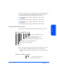
2 Combine the two binary fields into 8 bits and convert back to decimal:
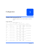
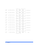
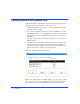
Loop IDs and Hardware Paths by Enclosure ID
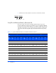
The rotary switch on the LCC set the Fibre-Channel Address range for the
enclosure. Both LCCs should be set identically for proper redundancy. Multiple
enclosures need to have unique settings to avoid address conflicts. If devices are
physically present and are not reported as found, suspect address conflicts with
other devices. The following tables helps understand what addressing is being
used:
0 0 1 0 1 1 1 0
32 + 8+4+2 = 46
Upper bit Lower bit
Table 8. Loop IDs and Hardware Paths by Slot Number and Enclosure ID 0 - 2
Encl.
ID
0 1 2
Disk
Slot #
(dec)
Loop
ID
(dec)
Bus
(dec)
Tgt
(dec)
ALPA
(hex)
Loop
ID
(dec)
Bus
(dec)
Tgt
(dec)
ALPA
(hex)
Loop
ID
(dec)
Bus
(dec)
Tgt
(dec)
ALPA
(hex)
1 000EF1610CD3220B2
2 101 E81711CC3321B1
3 200 E41812CB3422AE
4 303 E21913CA3523AD
5 404 E12014C93624AC
6 505 E02115C73725AB
7 606DC2216C63826AA
8 707DA2317C53927A9
9 808D92418C34028A7
10 9 0 9 D6251 9 BC412 9 A6