
User`s guide


76 Installation
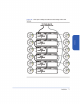
1 Determine which slots, 1 through 15, will contain disk modules and which
will contain fillers.
At least two slots must contain disk modules.
2 Put on the ESD strap and attach the other end of the strap appropriately.
Caution Disk modules are fragile. Handle carefully. Be careful to grasp the
disk module by its handle and avoid touching exposed circuitry.
3 Remove a disk module from the disk pack and its ESD bag.
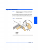
4 Open the disk module cam latch (C) by pulling the tab toward you.
5 Push the disk module as far as it will go into the selected slot.
6 Close the cam latch by pushing the latch toward the disk until it clicks. The
cam action draws the disk module completely into the slot and seats the
connecting pins on the midplane.
7 Repeat steps 4 through 6 to install additional disk modules.
8 Install disk fillers in the remaining slots.
Caution Every slot must contain either a disk module or filler.
Step 8: Turn on the Disk System
Caution When starting up the disk system, do not override automatic spin-
up of the drives. Doing so could cause an overcurrent fault,
requiring a power cycle to recover.
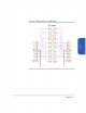
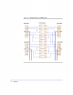
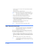
Press in the power/standby switch with the retracted tip of a pen or pencil to
power-on the disk system (see Figure 49). Allow 2 minutes for the disk drives
and controllers to complete their self-tests.
1 Press the power/standby switch (C in Figure 49) to turn on the disk system.
2 Watch the system LEDs for confirmation that the disk system is operational.
The system power LED (A) should be green, and the fault LED (B) should be
off.
If the LEDs indicate a problem, refer to chapter 4, Troubleshooting.
Note An amber light that is on briefly when a component turns on is
normal. If this light remains on more than a couple seconds, a fault
has been detected.