
User`s guide

Removal and Replacement 119
Removal and Replacement
7 Set address switches on the new LCC to match settings on the peer LCC.
Caution The address switches must have the same settings on both LCCs.
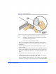
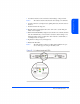
8 Open the cam levers (see Figure 58) by pulling them away from the center of
the card.
9 Insert the LCC in the empty slot.
10 Push the cam levers flat against the center of the card to seat the LCC pins
firmly on the midplane.
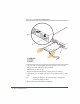
11 Watch the LCC Fault LED (see Figure 59). It should come on briefly and then
turn off. If the LED stays on and a buzzer sounds, the switch settings do not
match the settings on the peer LCC. For other solutions to a LCC fault, see
“Isolating Causes” in chapter 4.
12 Tighten the locking screws (A in Figure 58).
13 Reattach the FC cables.
Caution The LCC must be replaced or a filler panel installed in the open
slot to ensure proper cooling for the disk system.