HP SureStore Virtual Array 7100 Quick Start Guide Edition E0201 Order Part Number: A6183-90901 www.hp.
Notice Typographical Conventions © Hewlett-Packard Company, 2001. All rights reserved. Hewlett-Packard Company makes no warranty of any kind with regard to this document, including, but not limited to, the implied warranties of merchantability and fitness for a particular purpose. Hewlett-Packard shall not be liable for errors contained herein or for incidental or consequential damages in connection with the furnishing, performance, or use of this material.
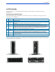
1 In This Guide In This Guide This guide shows how to install the HP SureStore Virtual Array 7100 deskside, field-rackable, and factoryracked products. Summary of Installation Steps: Follow the installation steps in the table below. Check them off as they are completed. (Some steps may not be necessary for your configuration.) ✔ Section A B C D E F G H Installation Step* Unpack the array. Is your array a field-rackable product? If YES, install the array into a rack. If NO, go to Section C.
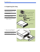
2 A. Unpacking the Array A. Unpacking the Array NOTE: If you are installing a factoryracked array, skip steps 1 through 6 and go to directly to step 7. 1. Quick Start Guide User’s Guide Unpack the array. Power Cords NOTE: Follow the instructions on top of the shipping container. 2. Serial Cable Check the contents of the shipping container (see Fig. 5). Optical Fibre Cable VA7100 Array Fig. 5. Checking the shipping container contents 3.
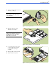
3 A. Unpacking the Array 4. Remove all of the disk drives from the array (see Fig. 7). CAUTION! Do NOT stack disk drives; damage to disk drives may occur if they fall. Fig. 7. Removing a disk drive 5. Place the disk drives on the antistatic mat (see Fig. 8). CAUTION! Do NOT mix disk drives among arrays. Disk drives must be reinstalled into the same array from which they were removed. Fig. 8. Placing disk drives on the antistatic mat 6.
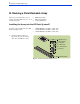
4 B. Racking a Field-Rackable Array B. Racking a Field-Rackable Array Follow the procedures in this section to install your field-rackable array into one of the following racks: • • • HP Rack System/E HP Computer Cabinet Compaq 9000 Rack Installing the Array into the HP Rack System/E Your array can be installed into these HP Rack System/E products: 1. • • • J1500A HP Rack System/E41 (1.96m; 41U) J1501A HP Rack System/E33 (1.60m; 33U) J1502A HP Rack System/E25 (1.
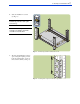
5 B. Racking a Field-Rackable Array 2. Study the installation overview (see Fig. 11). CAUTION! To ensure rack stability, install arrays from the bottom of the rack to the top. NOTE: The following tools are required for installation: flat-blade screwdriver and T25 driver. Fig. 11. HP Rack System/E Installation Overview 3. The array and rail kit take 3 units of space. Using the template provided, locate the required units of space on the four rack columns (see Fig. 12). Fig. 12.
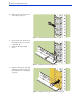
6 B. Racking a Field-Rackable Array 4. Install one clip nut on the inside of each column (see Fig. 13). Fig. 13. Installing rail clip nuts in HP Rack System/E 5. On the ends of the both rails, insert the rail tab (see Fig. 14, A) into the column hole (B). 6. Secure the rails with four M5 screws. B A Fig. 14. Installing rails in HP Rack System/E 7. Install one clip nut each on the right and left front columns (see Fig. 15). (Use the black arrow on the template as a guide.) Fig. 15.
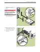
7 B. Racking a Field-Rackable Array 8. Place the array on the rails and slide it all the way to the rear. (see Fig. 16). WARNING! An empty array weighs in excess of 60 pounds (27.2 kg). To avoid serious injury, it is recommended that two people lift the array into the rack. 9. Tighten two M5 screws through the array front mounting ears. Fig. 16. Sliding the array into HP Rack System/E 10. Place two rail clamps on the rails and slide them into each rear corner of the array chassis. (see Fig. 17). 11.
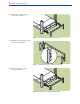
8 B. Racking a Field-Rackable Array 12. Remove the front bezel from the array chassis (see Fig. 18). Fig. 18. Removing front bezel in HP Rack System/E 13. Install the front bezel spacers inside the front bezel (see Fig. 19). Fig. 19. Installing bezel spacers in HP Rack System/E 14. Re-install the front bezel and spacers (see Fig. 20). Fig. 20.
9 B. Racking a Field-Rackable Array Installing the Array into the HP Computer Cabinet Your array can be installed into these HP Computer Cabinet products: CAUTION! To ensure a proper rack installation, use only these instructions for installing the HP Computer Cabinet rail kit. Ignore any instructions included in the rail kit box. 1. Check the rail kit contents (see Fig. 21). If any parts are missing, call your nearest HP sales office. • • • C2785A Computer Cabinet (1.
10 B. Racking a Field-Rackable Array 3. The array and rail kit take 4 units of space: 3 units for the array, and 1 unit for the rails (see Fig. 23). Using the template provided, locate the required units of space on the four rack columns. Fig. 23. Locating units of space in HP Computer Cabinet 4. Install one clip nut on the inside of each column (see Fig. 24). Fig. 24. Installing rail clip nuts in HP Computer Cabinet 5. On the ends of both rails, insert the rail tab (see Fig.
11 B. Racking a Field-Rackable Array 7. Install one clip nut each on the right and left front columns (see Fig. 26). (Use the black arrow on the template as a guide.) Fig. 26. Installing enclosure clip nuts in HP Computer Cabinet 8. Place the array on the rails and slide it all the way to the rear (see Fig. 27). WARNING! An empty array weighs in excess of 60 pounds (27.2 kg). To avoid serious injury, it is recommended that two people lift the array into the rack. 9.
12 B. Racking a Field-Rackable Array 10. Install a filler panel in the space below the array (see Fig. 28). Fig. 28.
13 B. Racking a Field-Rackable Array Installing the Array into the Compaq 9000 Rack Your array can be installed into these Compaq 9000 Rack products: • • • Rack 9142 (2.0m; 42U) Rack 9136 (1.7m; 36U) Rack 9122 (1.1m; 22U) CAUTION! To ensure a proper rack installation, use only these instructions for installing the HP Computer Cabinet rail kit. Ignore any instructions included in the rail kit box. 1.
14 B. Racking a Field-Rackable Array 3. The array and rail kit take 3 units of space. Using the template provided, locate the required units of space on the four rack columns (see Fig. 31). Fig. 31. Locating units of space in Compaq 9000 4. Holding the right rail in position, align the notches in the rail tab and mark the mounting hole on the front column (see Fig. 32). Fig. 32. Marking mounting holes in Compaq 9000 5.
15 B. Racking a Field-Rackable Array 7. Drop the rail tab lower notches onto the locating rod (see Fig. 34). Slide the locating rod clips against the mounting tabs at each end of the rod. (The clips prevent the rod from sliding out of the column.) 8. Repeat steps 4 through 7 for the left rail. Fig. 34. Positioning rails over locating rods in Compaq 9000 9. Insert a 5/16-18 sheet metal nut in each marked hole on the columns (see Fig. 35). Use a flat-blade screwdriver to assist in installing the nuts.
16 B. Racking a Field-Rackable Array 12. Place the array on the rails and slide it all the way to the rear. (see Fig. 37). WARNING! An empty array weighs in excess of 60 pounds (27.2 kg). To avoid serious injury, it is recommended that two people lift the array into the rack. 13. Tighten two 10-32 screws through the array front mounting ears. Fig. 37.
17 C. Connecting the Power and Fibre Channel Cables C. Connecting the Power and Fibre Channel Cables 1. Reinstall the disk drives and power supplies. 2. Connect one end of each power cord to the array ac power receptacle (see Fig. 38), and the other end to one of these ac power outlets: • • Separate ac circuits. • For racked arrays, separate power distribution units (PDUs). Separate uninterruptible power supplies (UPSs). Fig. 38. Connecting power cords for high availability 3.
18 D. Connecting the Serial Cable D. Connecting the Serial Cable NOTE: If you need to change the array host port behavior or the array loop IDs, follow the steps in this section. Otherwise, go to Section E. Changing the array host port behavior: If your array is connected to a host that is running Windows 2000, Windows NT, or Linux, you need to change the array host port behavior using the Virtual Front Panel (VFP).
19 E. Powering-On the Array E. Powering-On the Array 1. Press in the power/standby switch with the retracted tip of a pen or pencil to power-on the array (see Fig. 42). Allow 2 minutes for the disk drives and controllers to complete their self-tests. System Activity LED (Green) System Fault LED (Amber) NOTE: Disk drives are not visible on the bus until they have completed their self-tests. 2. Verify that the system activity LED is ON and the disk drive activity LEDs are ON (both green).
20 F. Changing the Array Host Port Behavior F. Changing the Array Host Port Behavior NOTE: If your array is connected to a host that is running Windows 2000, Windows NT, or Linux, you need to change the array host port behavior, using the Virtual Front Panel (VFP). If your array is connected to a host that is running HP-UX, you do not need to change the host port behavior setting. 1.
21 G. Changing the Array Loop IDs G. Changing the Array Loop IDs NOTE: Your array comes preset with the following default fibre channel loop identifiers (IDs): 108 (controller 1) and 110 (controller 2). If the default loop IDs conflict with the loop IDs of any other devices in your configuration, you need to change the array loop IDs using the Virtual Front Panel (VFP). If they do NOT conflict with other loop IDs, you do not need to change the array loop ID settings. 1.
22 H.