
Technical data


Maintenance Procedures 63
6. Remove all the GBICs from the faulty switch.
Note
Refer to the GBIC manufacturer’s documentation for specific
instructions about inserting and removing GBICs.
Installing the New Switch in the Chassis
7. Insert the GBICs into the new switch, inserting each GBIC into the port
until it is firmly seated and the latching mechanism becomes locked.
The GBIC module is keyed so that it can be inserted in one way only. If
the module does not slide in easily, try reversing it. The GBIC
D-connector must line up with the D-connector inside the GBIC port.
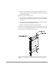
8. Install the mounting brackets on the new switch.
a. Position one of the brackets flat against the side of the switch, so that
the end with the bent lip is at the front of the switch (see Figure 23),
and align the holes in the bracket with the holes in the side of the
switch.
b. To ensure correct bracket alignment, assemble screws in the following
pattern:
Position and finger tighten the first 8/32 x .312 panhead Phillip
screw in the smallest hole in the bracket.
Position and finger tighten the second 8/32 x .312 panhead Phillip
screw in the oblong (slotted) hole.
Position and finger tighten the remaining two 8/32 x .312 panhead
Phillip screws in the remaining two holes.
Tighten all four screws to a torque of 8 inch-pounds.
c. Repeat Steps a through b with the second bracket on the other side of
the switch.
9. Install the new switch in the chassis.
a. Orient the switch so that the power connector is at the bottom of the
chassis (see Figure 23), and slide the switch into the available space.
b. Tighten the two self-retaining screws that fasten the switch brackets
to the chassis, using a number 2 Phillips screwdriver to tighten to 40
inch-pounds.