
Technical data


Installing and Configuring the FC 6164 33
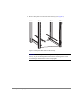
Note
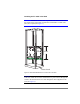
In these instructions, the 15 RUs used to mount the switch are called
RU-1 through RU-15 (see Figure 5); RU-1 is the lowest of the 15 RUs.
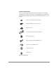
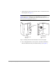
1. Check the contents of the shipping carton and the kits within the carton
to verify that all of the required parts and hardware are available (see
Figure 3, Table 7, and Figure 5).
2. Choose a mounting location in the rack for the switch (see the WARNING
at the beginning of this section and Figure 5).
3. Install the rail tray in the rack:
a. Locate the lowest RU of the 15 you chose for mounting the switch
(this is RU-1).
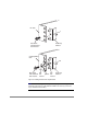
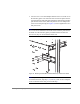
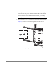
b. Attach the rear rail-tray brackets to the rear rack uprights at RU-1:
For an HP rack, use 1 M5 torx screw for each bracket (see Figure 6).
For a Compaq/Rittal rack, insert spacers in the upper and lower holes
where the brackets are to be mounted, position the brackets on the
spacers, and use 1 M5 torx screw with captive lock washer and two
M5 flat washers to attach each bracket (see Figure 6).