
Technical data
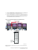


2. Use BN39B-04 (4 meters; 13.1 feet) or BN39B-10 (10 meters; 32.8 feet)
to connect the Memory Channel adapters of member systems 6, 7, and 8
to the Memory Channel hub.
3. Refer to the hardware manuals and install the network adapters for the
public network on member systems 6, 7, and 8. The public network is
not shown in the illustrations in this chapter.
4. Referring to Table 9–3, install a KZPBA-CB host bus adapter on
member system 6, 7, and 8. These host bus adapters will be used to
form a shared SCSI bus with member system 1.
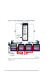
Ensure that you set the host bus adapter SCSI IDs as follows:
• Member system 1: SCSI bus ID 7 (which should already be set)
• Member system 6: SCSI bus ID 6
• Member system 7: SCSI bus ID 5
• Member system 8: SCSI bus ID 4
5. Ensure that each system (member system 6, 7, and 8) has a BN21W-0B
Y cable attached to the KZPBA-CB host bus adapter.
6. Ensure that there is an H879-AA terminator attached to one leg of the
BN21W-0B on member system 8. Member systems 1 and 8 will be at
the end of this shared SCSI bus.
7. Prepare the UltraSCSI BA356 for TruCluster Server use (See
Section 10.4.1.3.) Ensure that you have installed an H8861-AA VHDCI
trilink connector on the UltraSCSI BA356 personality module.
____________________ Note _____________________
If you need more storage than one UltraSCSI BA356
provides, you can daisy-chain two of them together. See
Section 10.4.3.3 for more information.
8. Connect a BN21K, BN21L, or 328215-00X cable between the BN21W-0B
Y cables on member system 1 and member system 6.
9. Connect a BN21K, BN21L, or 328215-00X cable between the BN21W-0B
Y cables on member system 7 and member system 8.
10. Connect a BN38C, BN38D, or a combination of a BN38E-0B technology
adapter cable and a BN37A cable between the open leg of the BN21W-0B
on member systems 6 and 7 to the H8861-AA VHDCI trilink connector
on the UltraSCSI BA356 personality module.
Configuring an Eight-Member Cluster Using Externally Terminated
Shared SCSI Buses 11–13