
Technical data
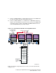
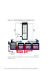


Table 11–2: Hardware Components Used for Configuration Shown Figure
11–3
Callout Number
Description
1
BN21W-0B HD68 Y cable
2
H879-AA HD68 terminator
3
BN21K, BN21L, or 328215-00X HD68 to HD68 cable
a
4
H8861-AA VHDCI trilink connector
5
BN38C or BN38D HD68 to VHDCI cable
ab
6
BN39B-04 or BN39B-10 Memory Channel cable
a
The maximum combined length of the BN21K, BN21L, 328215-00X, BN38C, BN38D, BN38E-0B, and
BN37A cables on one SCSI bus segment must not exceed 25 meters (82 feet).
b
A BN38E-0B technology adapter cable may be connected to a BN37A cable and used in place of a BN38C
or BN38D cable.
11.2.3 Cabling the Third Externally Terminated Shared SCSI Bus
So far, you have configured a two-node externally terminated shared SCSI
bus made up of member systems 1 and 2, and an externally terminated
four-node shared SCSI bus with member systems 2, 3, 4, and 5. You need
to configure a third externally terminated four-node shared SCSI bus to
complete your eight-node shared SCSI cluster.
This section covers the steps needed to configure member systems 1, 6, 7,
and 8 on an externally terminated shared SCSI bus.
Figure 11–4 shows a detailed illustration of member systems 1, 6, 7, and 8
on a shared SCSI bus. Table 11–3 lists the components needed to configure
the systems shown in Figure 11–4.
To configure member systems 1, 6, 7, and 8 on a four-node shared SCSI
bus, follow these steps:
1. Install the Memory Channel adapters on member systems 6, 7, and 8.
See Chapter 5 for installation and jumper information on the Memory
Channel adapters. Delay testing the Memory Channel until you have
installed all hardware.
____________________ Note _____________________
If member systems 1 and 2 are running cluster software, you
should not run mc_cable Memory Channel diagnostics. Shut
all systems down to the console level to run the mc_cable
diagnostic.
11–12 Configuring an Eight-Member Cluster Using Externally Terminated Shared SCSI Buses