
Technical data
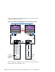
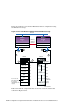
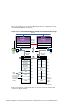
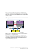
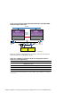

Figure 10–13: Externally Terminated Shared SCSI Bus with HSZ50 RAID
Array Controllers at Bus End
KZPSA-BB (ID 7)
Network
Memory
Channel
Interface
Memory Channel
KZPSA-BB (ID 6)
Memory Channel
Member
System
2
Member
System
1
2
1
1
2
T
T
3
4
3
3
4
HSZ50
Controller A Controller B
HSZ50
ZK-1597U-AI
Table 10–3 lists the components that are used to create the cluster that is
shown in Figure 10–12 and Figure 10–13.
Table 10–3: Hardware Components Used for Configuration Shown in
Figure 10–12 and Figure 10–13
Callout Number
Description
1
BN21W-0B Y cable
2
H879-AA terminator
3
BN21K (or BN21L) cable
ab
4
H885-AA trilink connector
a
The maximum combined length of the BN21K (or BN21L) cables must not exceed 25 meters (82 feet).
b
The cable between the H885-AA trilink connectors on the HSZ50s could be a BN21L-0B, a 15-centimeter
(5.9-inch) cable.
10–28 Configurations Using External Termination or Radial Connections to Non-UltraSCSI Devices