
Technical data


pass-through mechanism and cable to the library robotics motor are not
shown in this figure.
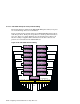
For more information on cabling the units, see Section 8.12.2.1.2. With the
exception of the robotics control on the expansion module, a rackmount
TL881 or TL891 DLT MiniLibrary is cabled in the same manner as a
tabletop unit.
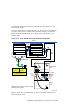
Figure 8–19: TL891 DLT MiniLibrary Rackmount Configuration
KZPBA-CB (ID 7)
Memory
Channel
Interface
Memory Channel
KZPBA-CB (ID 6)
Member System 1
DS-DWZZH-03
T
T
T
2
1
4
1
3
StorageWorks
RAID Array 7000
HSZ70HSZ70
Controller B Controller A
T
KZPBA-CB (ID 7)
5
5
6
7
7
KZPBA-CB (ID 6)
T
T
Network
T
NOTE: Robotic motor and pass through
mechanism not shown.
Member System 2
Memory Channel
KZPBA-CB (ID 6)
KZPBA-CB (ID 7)
T
5
Data
Unit
Expansion
Unit
Library
Robotics
Robotics
Control
cables
Diag
DLT2
Diag
Motor
SCSI
6
DLT1
TL891
Base
Unit
6
0.3 Meter
Jumper
Cable
7
ZK-1628U-AI
Expansion Modules
Table 8–20 list the components that are used to create the cluster that is
shown in Figure 8–19.
Configuring a Shared SCSI Bus for Tape Drive Use 8–69