
Technical data
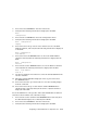
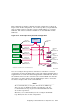

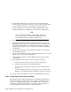

This configuration, which is called the four-bus configuration, is shown in
Figure 8–12. In this configuration, each of the tape drives, except SCSI bus
drive 0 and the robotics controller, requires a SCSI address on a separate
SCSI bus. The robotics controller and drive 0 use two SCSI IDs on their
SCSI bus.
Figure 8–12: TL894 Tape Library Four-Bus Configuration
Robotics Controller
*SCSI Address 0
Rear Panel
Host
Connection #1
SCSI Port 1
SCSI Port 2
SCSI Port 3
SCSI Port 4
Tape Drive 0
*SCSI Address 2
Tape Drive 1
*SCSI Address 3
Tape Drive 2
*SCSI Address 4
Tape Drive 3
*SCSI Address 5
Tape Drive
Interface PWA
SCSI Cable
1.5m
SCSI Cable
3m
Internal SCSI
Termination #1
Internal SCSI
Termination #2
Internal SCSI
Termination #3
Internal SCSI
Termination #4
Rear Panel
Host
Connection #2
Rear Panel
Host
Connection #3
Rear Panel
Host
Connection #4
ZK-1324U-AI
* - Indicates the "default" SCSI ID of the installed devices
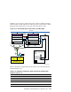
You can reconfigure the tape drives and robotics controller in a two-bus
configuration by using the SCSI jumper cable (part number 6210567) that is
supplied in the accessories kit that is shipped with each TL894 unit. Remove
the terminator from one drive and remove the internal SCSI cable from the
other drive to be daisy chained. Use the SCSI jumper cable to connect the
two drives and place them on the same SCSI bus.
______________________ Notes ______________________
We recommend that you not place more than two TZ89 tape
drives on any one SCSI bus in these tape libraries. We also
recommend that storage be placed on shared SCSI buses that
do not have tape drives.
Therefore, we recommend that you not reconfigure the TL894
tape library into the one-bus configuration.
Configuring a Shared SCSI Bus for Tape Drive Use 8–41