
Technical data

SCSI bus without stopping all ASE services that generate activity
on the bus.
For this reason, we recommend that tape devices be placed on
separate shared SCSI buses, and that there be no storage devices
on the SCSI bus.
The cabling depends on whether or not there are one or two drives, and for
the two-drive configuration, if each drive is on a separate SCSI bus.
______________________ Note _______________________
It is assumed that the library robotics controller is on the same
SCSI bus as tape drive 1.
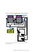
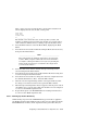
To connect the library robotics and one drive to a single shared SCSI bus,
follow these steps:
1. Connect a BN21K or BN21L between the last trilink connector on the
bus to the leftmost connector (as viewed from the rear) of the TL891.
2. Install a 30-centimeter (11.8-inch) SCSI bus jumper between the
rightmost robotics connector (second connector from the left) and the
left DLT1 connector (the third connector from the left).
3. Install an H879-AA terminator on the right DLT1 connector (the fourth
connector from the left).
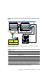
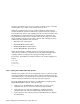
To connect the drive robotics and two drives to a single shared SCSI bus,
follow these steps:
1. Connect a BN21K or BN21L between the last trilink connector on the
bus to the leftmost connector (as viewed from the rear) of the TL892.
2. Install a 30-centimeter (11.8-inch) SCSI bus jumper between the
rightmost robotics connector (the second connector from the left) and
the left DLT1 connector (the third connector from the left).
3. Install a 30-centimeter (11.8-inch) SCSI bus jumper between the
rightmost DLT1 connector (the fourth connector from the left) and the
left DLT2 connector (the fifth connector from the left).
4. Install an H879-AA terminator on the right DLT2 connector (the
rightmost connector).
Configuring a Shared SCSI Bus for Tape Drive Use 8–27