
Technical data
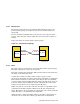
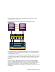
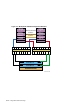
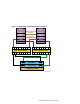


Figure 6–4 shows a typical Fibre Channel cluster configuration using
transparent failover mode.
Figure 6–4: Fibre Channel Single Switch Transparent Failover
Configuration
ZK-1531U-AI
KGPSA
Member
System
1
Memory
Channel
KGPSA
Memory
Channel
Memory
Channel
Interface
Member
System
2
Fibre Channel Switch
HSG 80
Controller A
HSG 80
Controller B
RA8000/ESA12000
Port 1
Port 2
Port 1 Port 2
In transparent failover, units D00 through D99 are accessed through port 1
of both controllers. Units D100 through D199 are accessed through port 2
of both HSG80 controllers.
You cannot achieve a no-single-point-of-failure (NSPOF) configuration using
transparent failover. The host cannot initiate failover, and if you lose a host
bus adapter, switch or hub, or a cable, you lose the units behind at least
one port.
You can, however, add the hardware for a second bus (another KGPSA,
switch, and RA8000/ESA12000 with associated cabling) and use LSM to
mirror across the buses. However, because you cannot use LSM to mirror
the member boot partitions or the quorum disk you cannot obtain an
NSPOF transparent failover configuration, even though you have increased
availability.
Using Fibre Channel Storage 6–9