
Technical data
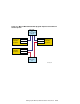
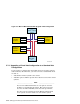


Table 5–5: Upgrading from a Virtual Hub Configuration to a Standard Hub
Configuration (cont.)
Step
Action Refer to:
______________________ Note ______________________
When system1 is at the console prompt, note the setting of the
auto_action console environment variable, then use the console set
command to set the auto_action variable to halt. This halts the
system at the console prompt when the system is turned on, ensuring
that you are able to run the Memory Channel diagnostics.
P00>>> show auto_action
.
.
.
P00>>> set auto_action halt
4
Turn off system1 power.
—
5
Disconnect the Memory Channel cables from system1.
—
6
Wearing an antistatic wrist strap, remove the
Memory Channel adapter modules and place them
on a grounded work surface.
—
7
On each Memory Channel adapter module, move the hub
mode jumper (J4 for MC1 or MC1.5 and J1 for MC2)
to pins 1 and 2 to select standard hub mode.
Section 5.1 and
Memory Channel
User’s Guide
______________________ Note ______________________
If you are also adding Memory Channel fiber optics capabilities, ensure
that Memory Channel adapter module J10 and J11 jumpers are set to
enable fiber optics.
8
Reinstall the Memory Channel modules. Section 5.2
9
If you are adding fiber optics, install the optical
converters in the member system.
Section 5.3
______________________ Note ______________________
Install the fiber-optic cable in cable runs between the hub and member
system. Connect the fiber-optic cable to the optical converter when you
install the converter in the system.
Connect the fiber-optic module to the Memory Channel adapter module
with a 1-meter (3.3-foot) FN39B-01 link cable.
10
Connect the Memory Channel cables between the Memory
Channel adapter module and the Memory Channel hub
and turn on hub power. If you have multiple adapters,
each adapter must be connected to a different hub, and
be in the same linecard slot position in each hub.
Section 5.5
5–28 Setting Up the Memory Channel Cluster Interconnect