
Technical data
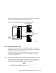

5.5.2.4 Connecting MC2 Cables in Standard Hub Mode Using Optical Converters
If you are using optical converters in an MC2 configuration, install an optical
converter module (CCMFB), with attached BN34R fiber-optic cable, when
you install the CCMAB Memory Channel PCI adapter in each system in the
standard hub configuration. Also connect the CCMAB Memory Channel
adapter to the optical converter with a BN39B-01 cable.
______________________ Note _______________________
See Section 2.2 for restrictions on the lengths of Memory Channel
fiber-optic cables.
Now you need to:
• Set the CCMLB linecard jumpers to support fiber optics
• Connect the fiber-optic cable to a CCMFB fiber-optic converter module
• Install the CCMFB fiber-optic converter module for each fiber-optic link
______________________ Note _______________________
If you have more than four fiber-optic links, you need two or more
hubs. The CCMHB-BA hub has no linecards.
To set the CCMLB jumpers and install CCMFB fiber-optic converter modules
in an MC2 hub, follow these steps:
1. Remove the appropriate CCMLB linecard and set the linecard jumpers
to Fiber On (jumper pins 1 to 2) to support fiber optics. See Table 5–3.
2. Remove the CCMLB endplate and install the alternate endplate (with
the slot at the bottom).
3. Remove the hub bulkhead blanking plate from the appropriate hub slot.
Ensure that you observe the slot restrictions for the optical converter
modules. Also keep in mind that all linecards for one Memory Channel
interconnect must be in the same hub. (See Section 5.4.)
4. Thread the BN34R fiber-optic cable through the hub bulkhead slot.
Make sure that the other end is attached to a CCMFB optics converter
in the member system.
5. Thread the BN34R fiber-optic cable through the slot near the bottom of
the endplate. Remove the cable tip protectors and insert the connectors
into the transceiver until they click into place. Secure the cable to the
module using the tie-wrap.
Setting Up the Memory Channel Cluster Interconnect 5–11