
Technical data

Do not connect an MC2 cable to an MC1 or MC1.5 CCMAA
module.
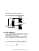
Gently push the cable’s connector into the receptacle, and then use the
screws to pull the connector in tight. The connector must be tight to ensure
a good ground contact.
If you are setting up redundant interconnects, all Memory Channel adapters
in a system must have the same jumper setting, either VH0 or VH1.
5.5.2.2 Installing MC2 Cables in Virtual Hub Mode Using Optical Converters
If you are using optical converters in an MC2 configuration, install an
optical converter module (CCMFB) when you install the CCMAB Memory
Channel PCI adapter in each system in the virtual hub configuration. Also
connect the CCMAB Memory Channel adapter to the optical converter with
a BN39B-01 cable. When you install the CCMFB optical converter module in
the second system, you connect the two systems with the BN34R fiber-optic
cable. Customer-supplied cables may be up to 2 kilometers (1.24 miles)
in length. (See Section 5.3.)
5.5.2.3 Connecting MC2 Link Cables in Standard Hub Mode (No Fiber Optics)
If there are more than two systems in a cluster, use a Memory Channel
standard hub configuration. Connect a BN39B-04 (4-meter; 13.1-foot) or
BN39B-10 (10-meter; 32.8-foot) link cable between the Memory Channel
adapter and a linecard in the CCMHB hub, starting at the lowest numbered
slot in the hub.
If you are setting up redundant interconnects, the following restrictions
apply:
• Each adapter installed in a system must be connected to a different hub.
• Each Memory Channel adapter in a system must be connected to
linecards that are installed in the same slot position in each hub. For
example, if you connect one adapter to a linecard installed in slot 0/opto
in one hub, you must connect the other adapter in that system to a
linecard installed in slot 0/opto of the second hub.
_____________________ Note _____________________
You cannot install a CCMLB linecard in slot opto only.
5–10 Setting Up the Memory Channel Cluster Interconnect