
Technical data

2. Install the Memory Channel adapter into a PCI slot on each system
(Section 5.2).
3. If you are using fiber optics with MC2, install the CCMFB fiber-optic
module (Section 5.3).
4. If you have more than two systems in the cluster, install a Memory
Channel hub (Section 5.4).
5. Connect the Memory Channel cables (Section 5.5).
6. After you complete steps 1 through 5 for all systems in the cluster, apply
power to the systems and run Memory Channel diagnostics (Section 5.6).
____________________ Note _____________________
If you are installing SCSI or network adapters, you may
want to complete all hardware installation before powering
up the systems to run Memory Channel diagnostics.
Section 5.7.2 provides procedures for upgrading from redundant MC1
interconnects to MC2 interconnects.
5.1 Setting the Memory Channel Adapter Jumpers
The meaning of the Memory Channel adapter module jumpers depends upon
the version of the Memory Channel module.
5.1.1 MC1 and MC1.5 Hub Mode Jumper
The MC1 and MC1.5 modules (CCMAA-AA and CCMAA-AB, respectively)
have an adapter jumper (J4) that designates whether the configuration is
using standard or virtual hub mode. If virtual hub mode is being used, there
can be only two systems. One system must be virtual hub 0 (VH0) and the
other must be virtual hub 1 (VH1).
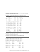
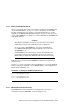
The Memory Channel adapter should arrive with the J4 jumper set for
standard hub mode (pins 1 to 2 jumpered). Confirm that the jumper is set
properly for your configuration. The jumper configurations in Table 5–1
are shown as if you are holding the module with the J4 jumper facing you,
with the module end plate in your left hand. The jumper is next to the
factory/maintenance cable connector.
5–2 Setting Up the Memory Channel Cluster Interconnect