
User guide
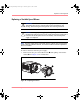
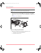
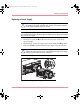
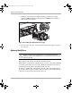

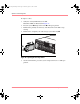
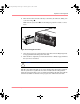
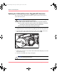
Table Of Contents
- MSA1000 User Guide
- Contents
- About this Guide
- Chapter 1: Introduction
- Chapter 2: Operating System Specific Information
- Chapter 3: MSA1000 Setup and Sample Configurations
- Chapter 4: Operation and Management
- Chapter 5: Array Configuration Utility (ACU)
- Installing the ACU on the Server
- Accessing the ACU
- Description of Screen Regions
- Configuring a New Controller
- Modifying an Existing Controller
- Probability of Logical Drive Failure
- Chapter 6: Command Line Interface (CLI)
- CLI Overview
- CLI Setup
- Help Commands
- Display Commands
- Array Controller Configuration Commands
- LUN Management Commands
- Server Connection Commands
- Selective Storage Presentation/Access Control List Commands
- Appendix A: Regulatory Compliance Notices
- Appendix B: Electrostatic Discharge
- Appendix C: Specifications
- Appendix D: Hard Drive Arrays
- Appendix E: Recovering from Hard Drive Failure
- Appendix F: Controller Display Messages
- Appendix G: Recovery ROM and ROM Cloning
- Appendix H: SCSI ID Assignments
- Index
Operation and Management
78 Modular SAN Array 1000 User Guide
Replacing the 2-Gb Small Form Factor Pluggable (SFP) Transceiver
If a transceiver fails, follow this procedure to replace it. It is not necessary to
power down the system.
WARNING: To reduce the risk of injury from laser radiation or damage to the
equipment, observe the following precautions:
■ Allow only HP Authorized Service Technicians to repair the equipment.
■ Do not open any panels, operate controls, make adjustments, or perform
procedures to a laser device other than those specified herein.
■ Do not stare into laser beam when panels are open.
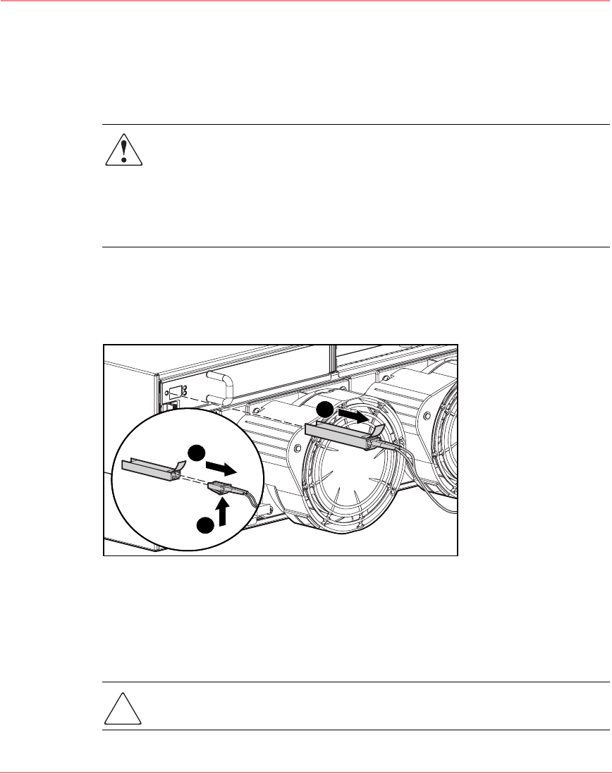
1. Pull the transceiver out of the device by pulling up and out on the plastic tab.
2. Press the release clip on the bottom of the cable connector 2 to remove the
Fibre Channel cable from the back of the failed transceiver 3.
Figure 41: Removing the failed SFP
3. Replace the protective covers on the cable and insert the dust plug covers into
the transceiver cage.
4. To insert a new SFP, reverse steps 1 through 3.
Caution: To reduce the risk of damage to the equipment, do not use excessive
force when inserting the transceiver.
1
2
3
230941-005_MSA1000_UG.book Page 78 Thursday, April 17, 2003 5:53 PM