
User guide

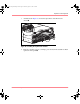
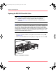
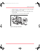
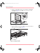
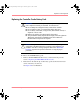
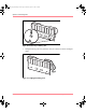

Table Of Contents
- MSA1000 User Guide
- Contents
- About this Guide
- Chapter 1: Introduction
- Chapter 2: Operating System Specific Information
- Chapter 3: MSA1000 Setup and Sample Configurations
- Chapter 4: Operation and Management
- Chapter 5: Array Configuration Utility (ACU)
- Installing the ACU on the Server
- Accessing the ACU
- Description of Screen Regions
- Configuring a New Controller
- Modifying an Existing Controller
- Probability of Logical Drive Failure
- Chapter 6: Command Line Interface (CLI)
- CLI Overview
- CLI Setup
- Help Commands
- Display Commands
- Array Controller Configuration Commands
- LUN Management Commands
- Server Connection Commands
- Selective Storage Presentation/Access Control List Commands
- Appendix A: Regulatory Compliance Notices
- Appendix B: Electrostatic Discharge
- Appendix C: Specifications
- Appendix D: Hard Drive Arrays
- Appendix E: Recovering from Hard Drive Failure
- Appendix F: Controller Display Messages
- Appendix G: Recovery ROM and ROM Cloning
- Appendix H: SCSI ID Assignments
- Index
Operation and Management
69Modular SAN Array 1000 User Guide
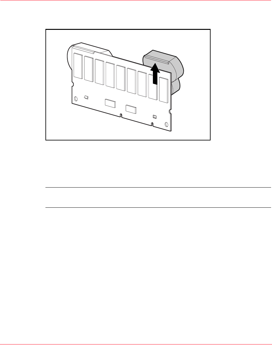
4. Lift the pack upward to unhook the top of the battery pack.
Figure 32: Removing the battery pack
Wait about 15 seconds after removing the old battery packs to allow the
battery charge monitor to reset.
Note: Repeat the replacement procedure for any batteries that were installed at the
same time as the batteries that were removed.
5. Install the new NiMH battery pack by hooking the top of the battery pack to
the top of the Array Accelerator with the pack held at a 30-degree angle to the
plane of the Array Accelerator board.
See Figure 33 for an illustration.
230941-005_MSA1000_UG.book Page 69 Thursday, April 17, 2003 5:53 PM