
User guide

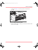
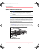
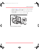
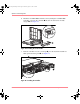
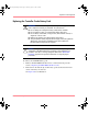

Table Of Contents
- MSA1000 User Guide
- Contents
- About this Guide
- Chapter 1: Introduction
- Chapter 2: Operating System Specific Information
- Chapter 3: MSA1000 Setup and Sample Configurations
- Chapter 4: Operation and Management
- Chapter 5: Array Configuration Utility (ACU)
- Installing the ACU on the Server
- Accessing the ACU
- Description of Screen Regions
- Configuring a New Controller
- Modifying an Existing Controller
- Probability of Logical Drive Failure
- Chapter 6: Command Line Interface (CLI)
- CLI Overview
- CLI Setup
- Help Commands
- Display Commands
- Array Controller Configuration Commands
- LUN Management Commands
- Server Connection Commands
- Selective Storage Presentation/Access Control List Commands
- Appendix A: Regulatory Compliance Notices
- Appendix B: Electrostatic Discharge
- Appendix C: Specifications
- Appendix D: Hard Drive Arrays
- Appendix E: Recovering from Hard Drive Failure
- Appendix F: Controller Display Messages
- Appendix G: Recovery ROM and ROM Cloning
- Appendix H: SCSI ID Assignments
- Index
Operation and Management
62 Modular SAN Array 1000 User Guide
Replacing the MSA1000 Controller
If an MSA1000 Controller is failing, informational or error messages will be
displayed on the LCD panel of that controller, depending on the condition.
The following steps detail how to replace a failed MSA1000 Controller, but can
also be used to re-seat the Controller.
Note: Redundancy is supported during a hard drive expansion, migration, or
extension process and during regular drive rebuilds.
Note: Replacement MSA1000 Controllers include a new cache module. Remove this
new module from the replacement MSA1000 Controller and replace it with the cache
module from the failed controller. Using the same cache module will complete the disk
writes that may have been trapped in the Controller’s cache. See “Replacing the
MSA1000 Controller Cache” for procedural instructions.
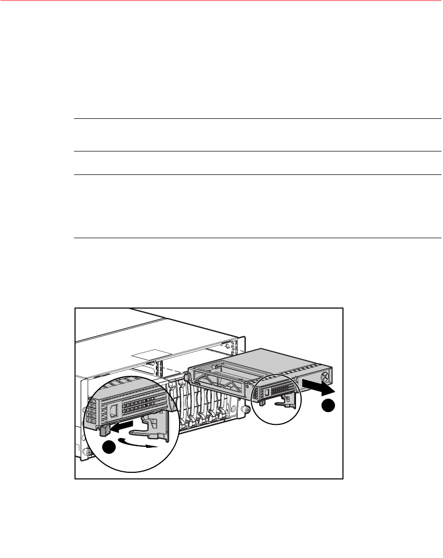
1. Press the controller’s thumb latch and pull the latch handle toward you 1.
2. Remove the MSA1000 Controller by pulling it straight out of the chassis 2,
as illustrated in Figure 24.
Figure 24: Removing the MSA1000 Controller
1
2
230941-005_MSA1000_UG.book Page 62 Thursday, April 17, 2003 5:53 PM