
User guide
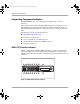

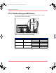
Table Of Contents
- MSA1000 User Guide
- Contents
- About this Guide
- Chapter 1: Introduction
- Chapter 2: Operating System Specific Information
- Chapter 3: MSA1000 Setup and Sample Configurations
- Chapter 4: Operation and Management
- Chapter 5: Array Configuration Utility (ACU)
- Installing the ACU on the Server
- Accessing the ACU
- Description of Screen Regions
- Configuring a New Controller
- Modifying an Existing Controller
- Probability of Logical Drive Failure
- Chapter 6: Command Line Interface (CLI)
- CLI Overview
- CLI Setup
- Help Commands
- Display Commands
- Array Controller Configuration Commands
- LUN Management Commands
- Server Connection Commands
- Selective Storage Presentation/Access Control List Commands
- Appendix A: Regulatory Compliance Notices
- Appendix B: Electrostatic Discharge
- Appendix C: Specifications
- Appendix D: Hard Drive Arrays
- Appendix E: Recovering from Hard Drive Failure
- Appendix F: Controller Display Messages
- Appendix G: Recovery ROM and ROM Cloning
- Appendix H: SCSI ID Assignments
- Index
Operation and Management
55Modular SAN Array 1000 User Guide
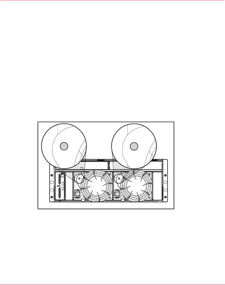
Power Supply/Blower Assembly Indicators
The green indicators on the power supply/blower assembly are on when both the
power supply and the blower are operational. When a power supply or blower
fault occurs, the power supply indicators go off. If the power supply indicators are
off, AC power is not present or there is a complete power supply failure.
The power supply-mounted blowers cool the enclosure by circulating air through
the enclosure and elements. The rate at which air moves (the airflow) determines
the amount of cooling. This airflow is a function of blower speed (rpm). These
blowers, under the control of the Environmental Monitoring Unit (EMU) or the
associated power supply, can operate at multiple speeds. This ensures that when
the enclosure temperature changes, the blowers can automatically adjust the
airflow.
If one blower operates too slowly or completely shuts off, the other blower will
begin to operate at a higher speed. At the same time, the error condition is
reported to LCD panel on the front of the Controller.
Figure 20: Power supply/blower assembly indicators
230941-005_MSA1000_UG.book Page 55 Thursday, April 17, 2003 5:53 PM