
User guide
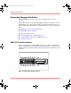
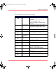

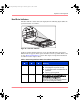
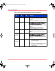
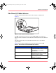
Table Of Contents
- MSA1000 User Guide
- Contents
- About this Guide
- Chapter 1: Introduction
- Chapter 2: Operating System Specific Information
- Chapter 3: MSA1000 Setup and Sample Configurations
- Chapter 4: Operation and Management
- Chapter 5: Array Configuration Utility (ACU)
- Installing the ACU on the Server
- Accessing the ACU
- Description of Screen Regions
- Configuring a New Controller
- Modifying an Existing Controller
- Probability of Logical Drive Failure
- Chapter 6: Command Line Interface (CLI)
- CLI Overview
- CLI Setup
- Help Commands
- Display Commands
- Array Controller Configuration Commands
- LUN Management Commands
- Server Connection Commands
- Selective Storage Presentation/Access Control List Commands
- Appendix A: Regulatory Compliance Notices
- Appendix B: Electrostatic Discharge
- Appendix C: Specifications
- Appendix D: Hard Drive Arrays
- Appendix E: Recovering from Hard Drive Failure
- Appendix F: Controller Display Messages
- Appendix G: Recovery ROM and ROM Cloning
- Appendix H: SCSI ID Assignments
- Index
Operation and Management
53Modular SAN Array 1000 User Guide
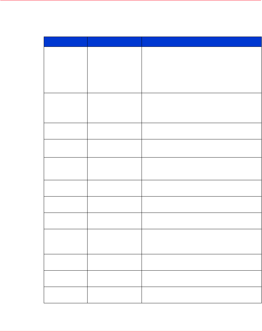
Table 8: MSA1000 Controller Indicator Descriptions
Indicator Function Description
0-2
Busy status These three LEDs are used to progressively
represent the processing load on the
controller.
ON = the controller is idle.
OFF = the controller is operating at full
capacity.
3-7
Fibre Channel ID Indicates the 5-bit Arbitrated Loop Physical
Address (ALPA) assigned to this array
controller (not applicable when in fabric
mode).
8 Idle Heartbeat Indicates the controller is idle and
functioning.
9
Active/Standby ON=Controller is active.
OFF=Controller is in standby.
-
Direct Memory
Access (DMA)
active
ON = DMA transfers are active.
q
Logical I/O active ON = Currently processing logical requests
from the Host Adapter.
w
SCSI Bus 0 active ON = Indicates requests are outstanding on
the first SCSI bus.
e
SCSI Bus 1 active ON = Indicates requests are outstanding on
the second SCSI bus.
r
Cache Activity ON = Cache active.
OFF = No cache activity.
Blinking = Cache transfer pending.
t
Drive failure ON = A configured hard drive has failed in
the array.
@
Redundancy
Active
Green indicates two controllers are in a
redundant mode of operation.
A
Fault Red indicates an error message has been
sent to the controller display.
230941-005_MSA1000_UG.book Page 53 Thursday, April 17, 2003 5:53 PM