
User guide

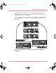
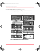

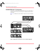

Table Of Contents
- MSA1000 User Guide
- Contents
- About this Guide
- Chapter 1: Introduction
- Chapter 2: Operating System Specific Information
- Chapter 3: MSA1000 Setup and Sample Configurations
- Chapter 4: Operation and Management
- Chapter 5: Array Configuration Utility (ACU)
- Installing the ACU on the Server
- Accessing the ACU
- Description of Screen Regions
- Configuring a New Controller
- Modifying an Existing Controller
- Probability of Logical Drive Failure
- Chapter 6: Command Line Interface (CLI)
- CLI Overview
- CLI Setup
- Help Commands
- Display Commands
- Array Controller Configuration Commands
- LUN Management Commands
- Server Connection Commands
- Selective Storage Presentation/Access Control List Commands
- Appendix A: Regulatory Compliance Notices
- Appendix B: Electrostatic Discharge
- Appendix C: Specifications
- Appendix D: Hard Drive Arrays
- Appendix E: Recovering from Hard Drive Failure
- Appendix F: Controller Display Messages
- Appendix G: Recovery ROM and ROM Cloning
- Appendix H: SCSI ID Assignments
- Index
MSA1000 Setup and Sample Configurations
43Modular SAN Array 1000 User Guide
Fibre Channel I/O Module Configurations
When using the included Fibre Channel I/O Module, the MSA1000 will usually
be connected to an external switch or hub. In Windows, Linux, and NetWare
environments only, the MSA1000 can be connected directly to a server.
Fiber optic cables are used to connect the MSA1000 to the server and SCSI cables
are used to connect the MSA1000 to the additional storage enclosures.
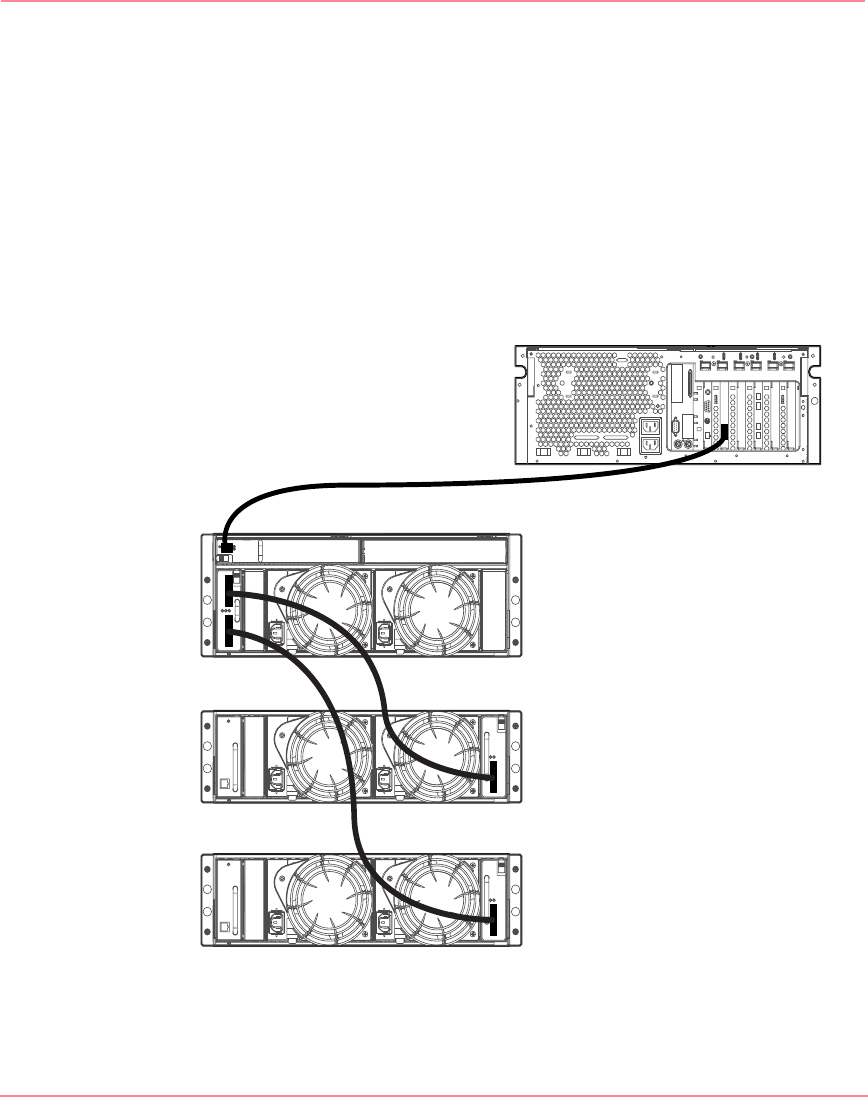
Figure 12 illustrates this basic configuration of connecting one server directly to
the Fibre Channel I/O Module of the MSA1000.
Figure 12: I/O module directly connected to a server
654321
Server
MSA1000
4314 storage enclosure
4314 storage enclosure
230941-005_MSA1000_UG.book Page 43 Thursday, April 17, 2003 5:53 PM