
User guide

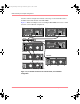
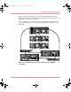
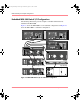

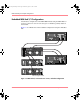

Table Of Contents
- MSA1000 User Guide
- Contents
- About this Guide
- Chapter 1: Introduction
- Chapter 2: Operating System Specific Information
- Chapter 3: MSA1000 Setup and Sample Configurations
- Chapter 4: Operation and Management
- Chapter 5: Array Configuration Utility (ACU)
- Installing the ACU on the Server
- Accessing the ACU
- Description of Screen Regions
- Configuring a New Controller
- Modifying an Existing Controller
- Probability of Logical Drive Failure
- Chapter 6: Command Line Interface (CLI)
- CLI Overview
- CLI Setup
- Help Commands
- Display Commands
- Array Controller Configuration Commands
- LUN Management Commands
- Server Connection Commands
- Selective Storage Presentation/Access Control List Commands
- Appendix A: Regulatory Compliance Notices
- Appendix B: Electrostatic Discharge
- Appendix C: Specifications
- Appendix D: Hard Drive Arrays
- Appendix E: Recovering from Hard Drive Failure
- Appendix F: Controller Display Messages
- Appendix G: Recovery ROM and ROM Cloning
- Appendix H: SCSI ID Assignments
- Index

MSA1000 Setup and Sample Configurations
42 Modular SAN Array 1000 User Guide
Identifying the Server Host Mode
For all operating system environments, after the arrays and logical volumes have
been created, each server’s operating system must be identified to the MSA1000.
The Host Mode can be set in both the ACU and the CLI.
For information on setting the Host Mode using the ACU, see the “Array
Configuration Utility (ACU)” chapter.
For information on setting the Host Mode using the CLI, see “Managing
Connection Profiles” in the “Command Line Interface (CLI)” chapter.
MSA1000 Sample Configurations
Because the MSA1000 supports a variety of embedded and external switches and
hubs in standalone and clustered deployments, many configuration options exist.
This section illustrates possible configurations using the following interconnect
options:
■ Fibre Channel I/O Module Configurations
■ Embedded MSA SAN Switch 2/8 Configurations
■ Embedded MSA Hub 2/3 Configurations
Note: Redundancy and cluster support is possible in all configurations.
Redundant configurations are used to ensure uninterrupted availability of data.
Complete duplication of all hardware components is a requirement of a redundant
configuration. This duplicity includes using two MSA controllers, and at least two
interconnect devices (depending on the configuration this may include MSA Fibre
Channel I/O Modules, MSA SAN Switch 2/8s, MSA Hub 2/3s, or external
switches or hubs), and HBAs in the server. As mentioned previously, the fiber
cables must be connected in a precise manner to provide the multiple paths
required when rerouting data.
The following illustrations provide samples of possible configurations, and are in
no way comprehensive.
230941-005_MSA1000_UG.book Page 42 Thursday, April 17, 2003 5:53 PM