
User guide
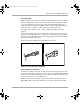
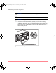
Table Of Contents
- MSA1000 User Guide
- Contents
- About this Guide
- Chapter 1: Introduction
- Chapter 2: Operating System Specific Information
- Chapter 3: MSA1000 Setup and Sample Configurations
- Chapter 4: Operation and Management
- Chapter 5: Array Configuration Utility (ACU)
- Installing the ACU on the Server
- Accessing the ACU
- Description of Screen Regions
- Configuring a New Controller
- Modifying an Existing Controller
- Probability of Logical Drive Failure
- Chapter 6: Command Line Interface (CLI)
- CLI Overview
- CLI Setup
- Help Commands
- Display Commands
- Array Controller Configuration Commands
- LUN Management Commands
- Server Connection Commands
- Selective Storage Presentation/Access Control List Commands
- Appendix A: Regulatory Compliance Notices
- Appendix B: Electrostatic Discharge
- Appendix C: Specifications
- Appendix D: Hard Drive Arrays
- Appendix E: Recovering from Hard Drive Failure
- Appendix F: Controller Display Messages
- Appendix G: Recovery ROM and ROM Cloning
- Appendix H: SCSI ID Assignments
- Index
MSA1000 Setup and Sample Configurations
37Modular SAN Array 1000 User Guide
Fiber Optic Cables
Multi-mode fiber optic cables are capable of supporting distances of 2 m to 500 m
(6.56 ft to 1640.42 ft) at 1 Gb and up to 300 m (984.25 ft) at 2 Gb. These cables
are for use with Short-wave transceivers only. Several multi-mode fiber optic
cable option kits are available from HP. Each kit contains a multi-mode fiber optic
cable with either a 1 Gb/s or a 2 Gb/s connector attached to each end.
For cables greater than 15 meters, contact an independent fiber optic cable
supplier.
If you use an existing 62.5-micron optical cable, you must obtain a 62.5-micron
jumper from an independent source. A 50-micron cable cannot be spliced with a
62.5-micron cable. In addition, these cables support half the maximum allowable
distance of the multi-mode cables.
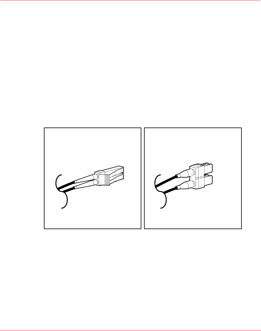
Figure 10 provides an illustration of the different connectors.
Figure 10: 2 Gb/s and 1 Gb/s connectors
Cable Installation Considerations
To ensure the cabling in the back of a rack system does not interfere with system
operation or maintenance, gather the cables in the rear of the MSA1000 and bind
them loosely with cable ties. Route the excess cables out of the way, along the side
of the rack. See Figure 11 for an illustration.
When the cables are tied together and the excess cable is routed away from the
MSA1000, system components and indicators are easily visible and accessible.
1Gb/s (SC) cable connector2Gb/s (LC) cable connector
230941-005_MSA1000_UG.book Page 37 Thursday, April 17, 2003 5:53 PM