
User guide

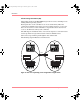

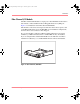
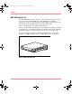
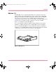
Table Of Contents
- MSA1000 User Guide
- Contents
- About this Guide
- Chapter 1: Introduction
- Chapter 2: Operating System Specific Information
- Chapter 3: MSA1000 Setup and Sample Configurations
- Chapter 4: Operation and Management
- Chapter 5: Array Configuration Utility (ACU)
- Installing the ACU on the Server
- Accessing the ACU
- Description of Screen Regions
- Configuring a New Controller
- Modifying an Existing Controller
- Probability of Logical Drive Failure
- Chapter 6: Command Line Interface (CLI)
- CLI Overview
- CLI Setup
- Help Commands
- Display Commands
- Array Controller Configuration Commands
- LUN Management Commands
- Server Connection Commands
- Selective Storage Presentation/Access Control List Commands
- Appendix A: Regulatory Compliance Notices
- Appendix B: Electrostatic Discharge
- Appendix C: Specifications
- Appendix D: Hard Drive Arrays
- Appendix E: Recovering from Hard Drive Failure
- Appendix F: Controller Display Messages
- Appendix G: Recovery ROM and ROM Cloning
- Appendix H: SCSI ID Assignments
- Index
Introduction
17Modular SAN Array 1000 User Guide
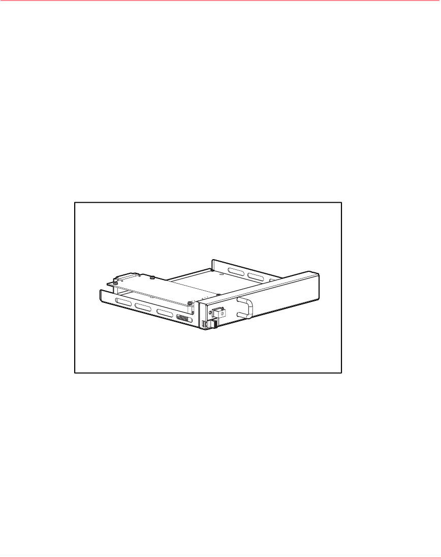
Fibre Channel I/O Module
The Fibre Channel I/O Module is a single-port, 1-Gb/2-Gb Fibre Channel device
that includes a 2 Gb/s Small Form Factor Pluggable Transceiver (SFP) port.
Figure 7 is an illustration of the Fibre Channel I/O Module.
This module can be removed and replaced with other interconnect options, such
as the MSA SAN Switch 2/8 or the MSA Hub 2/3. In redundant configurations,
the interconnect devices must be a matching pair.
If a second controller is added for additional functionality but not for system
redundancy, an MSA SAN Switch 2/8 or an MSA Hub 2/3 may be installed.
If you are using the Fibre Channel I/O Module and an additional controller is
installed for redundancy, a second I/O Module must be ordered and installed.
Figure 7: Fibre Channel I/O Module
230941-005_MSA1000_UG.book Page 17 Thursday, April 17, 2003 5:53 PM