
User guide

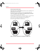

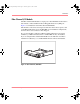
Table Of Contents
- MSA1000 User Guide
- Contents
- About this Guide
- Chapter 1: Introduction
- Chapter 2: Operating System Specific Information
- Chapter 3: MSA1000 Setup and Sample Configurations
- Chapter 4: Operation and Management
- Chapter 5: Array Configuration Utility (ACU)
- Installing the ACU on the Server
- Accessing the ACU
- Description of Screen Regions
- Configuring a New Controller
- Modifying an Existing Controller
- Probability of Logical Drive Failure
- Chapter 6: Command Line Interface (CLI)
- CLI Overview
- CLI Setup
- Help Commands
- Display Commands
- Array Controller Configuration Commands
- LUN Management Commands
- Server Connection Commands
- Selective Storage Presentation/Access Control List Commands
- Appendix A: Regulatory Compliance Notices
- Appendix B: Electrostatic Discharge
- Appendix C: Specifications
- Appendix D: Hard Drive Arrays
- Appendix E: Recovering from Hard Drive Failure
- Appendix F: Controller Display Messages
- Appendix G: Recovery ROM and ROM Cloning
- Appendix H: SCSI ID Assignments
- Index
Introduction
16 Modular SAN Array 1000 User Guide
Redundant Power Supply/Blower Assembly
The MSA1000 includes a redundant power supply. The redundant power supply is
identical to the primary supply and shares the electrical load equally. If either
supply fails or is removed, the other power supply assumes the full load without
interruption. Hot-pluggability allows you to replace the failed supply without
shutting the MSA1000 storage system down.
The MSA1000 includes a redundant blower. If one blower operates too slowly, or
completely shuts off, the other blower will begin to operate at a higher speed.
Any changes in the performance level of the power supply or blower are reported
on the LCD panel of the associated controller. For a description of the possible
informational and error messages associated with the power supplies or blowers,
see the definitions for messages numbered 400 through 499 in the “Controller
Display Messages” appendix.
Depending on the setup of Insight Manager 7 and Compaq Analyze, informational
and error messages about the power supplies and blowers are also reported though
these software components.
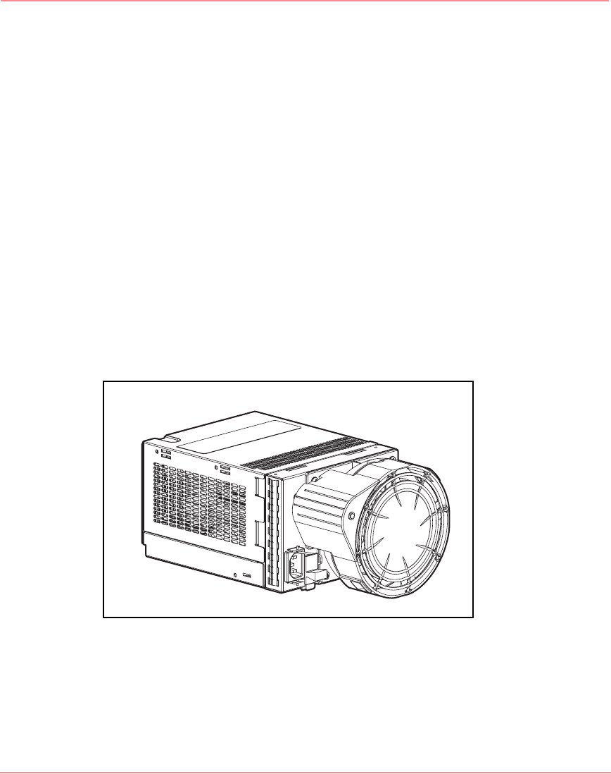
Figure 6 is an illustration of the power supply/blower assembly.
Figure 6: Power supply/blower assembly
Refer to the “Replacing a Power Supply” and “Replacing a Variable Speed
Blower” sections in the “Operation and Management” chapter for more
information.
230941-005_MSA1000_UG.book Page 16 Thursday, April 17, 2003 5:53 PM