
User guide
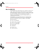
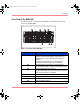
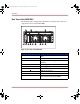
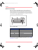
Table Of Contents
- MSA1000 User Guide
- Contents
- About this Guide
- Chapter 1: Introduction
- Chapter 2: Operating System Specific Information
- Chapter 3: MSA1000 Setup and Sample Configurations
- Chapter 4: Operation and Management
- Chapter 5: Array Configuration Utility (ACU)
- Installing the ACU on the Server
- Accessing the ACU
- Description of Screen Regions
- Configuring a New Controller
- Modifying an Existing Controller
- Probability of Logical Drive Failure
- Chapter 6: Command Line Interface (CLI)
- CLI Overview
- CLI Setup
- Help Commands
- Display Commands
- Array Controller Configuration Commands
- LUN Management Commands
- Server Connection Commands
- Selective Storage Presentation/Access Control List Commands
- Appendix A: Regulatory Compliance Notices
- Appendix B: Electrostatic Discharge
- Appendix C: Specifications
- Appendix D: Hard Drive Arrays
- Appendix E: Recovering from Hard Drive Failure
- Appendix F: Controller Display Messages
- Appendix G: Recovery ROM and ROM Cloning
- Appendix H: SCSI ID Assignments
- Index

Introduction
9Modular SAN Array 1000 User Guide
MSA1000 Hardware Components
The standard configuration of the MSA1000 includes one MSA1000 Controller,
one MSA Fibre Channel I/O Module, one SCSI I/O with an integrated EMU, and
redundant power supply/blower assemblies.
Option kits are available for redundant MSA1000 Controllers and Fibre
Channel I/O Modules as well as for embedded switches and hubs.
Components of the MSA1000 include:
■ MSA1000 Controller
■ SCSI I/O with integrated Environmental Monitoring Unit
■ Redundant power supply/blower assemblies
■ Fibre Channel I/O Module
■ MSA SAN Switch 2/8 (option only)
■ MSA Hub 2/3 (option only)
MSA1000 Controller
The MSA1000 Controller is a drive array controller specifically designed for
installation in the MSA1000. The MSA1000 comes equipped with one MSA1000
Controller installed. An additional controller for redundancy can be purchased
separately.
To ensure uninterrupted service, two copies of the controller firmware are stored
in Read Only Memory (ROM) on the controller. See the “Recovery ROM and
ROM Cloning” appendix for more information.
Additional information about the following topics is included in this section:
■ MSA1000 Controller Display
■ Array Accelerator (Battery-backed Cache)
■ Array Configuration
230941-005_MSA1000_UG.book Page 9 Thursday, April 17, 2003 5:53 PM