
User guide
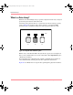
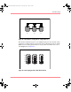
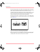
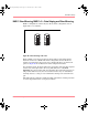
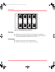
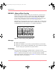
Table Of Contents
- MSA1000 User Guide
- Contents
- About this Guide
- Chapter 1: Introduction
- Chapter 2: Operating System Specific Information
- Chapter 3: MSA1000 Setup and Sample Configurations
- Chapter 4: Operation and Management
- Chapter 5: Array Configuration Utility (ACU)
- Installing the ACU on the Server
- Accessing the ACU
- Description of Screen Regions
- Configuring a New Controller
- Modifying an Existing Controller
- Probability of Logical Drive Failure
- Chapter 6: Command Line Interface (CLI)
- CLI Overview
- CLI Setup
- Help Commands
- Display Commands
- Array Controller Configuration Commands
- LUN Management Commands
- Server Connection Commands
- Selective Storage Presentation/Access Control List Commands
- Appendix A: Regulatory Compliance Notices
- Appendix B: Electrostatic Discharge
- Appendix C: Specifications
- Appendix D: Hard Drive Arrays
- Appendix E: Recovering from Hard Drive Failure
- Appendix F: Controller Display Messages
- Appendix G: Recovery ROM and ROM Cloning
- Appendix H: SCSI ID Assignments
- Index
Hard Drive Arrays
173Modular SAN Array 1000 User Guide
Figure 62: Physical drives configured into a logical drive (L1)
Because the read/write heads are active simultaneously, the same amount of data
is written to each drive during any given time interval. Each unit of data is called a
block, and over all the physical drives in a logical drive the blocks form a set of
data stripes (refer to Figure 63).
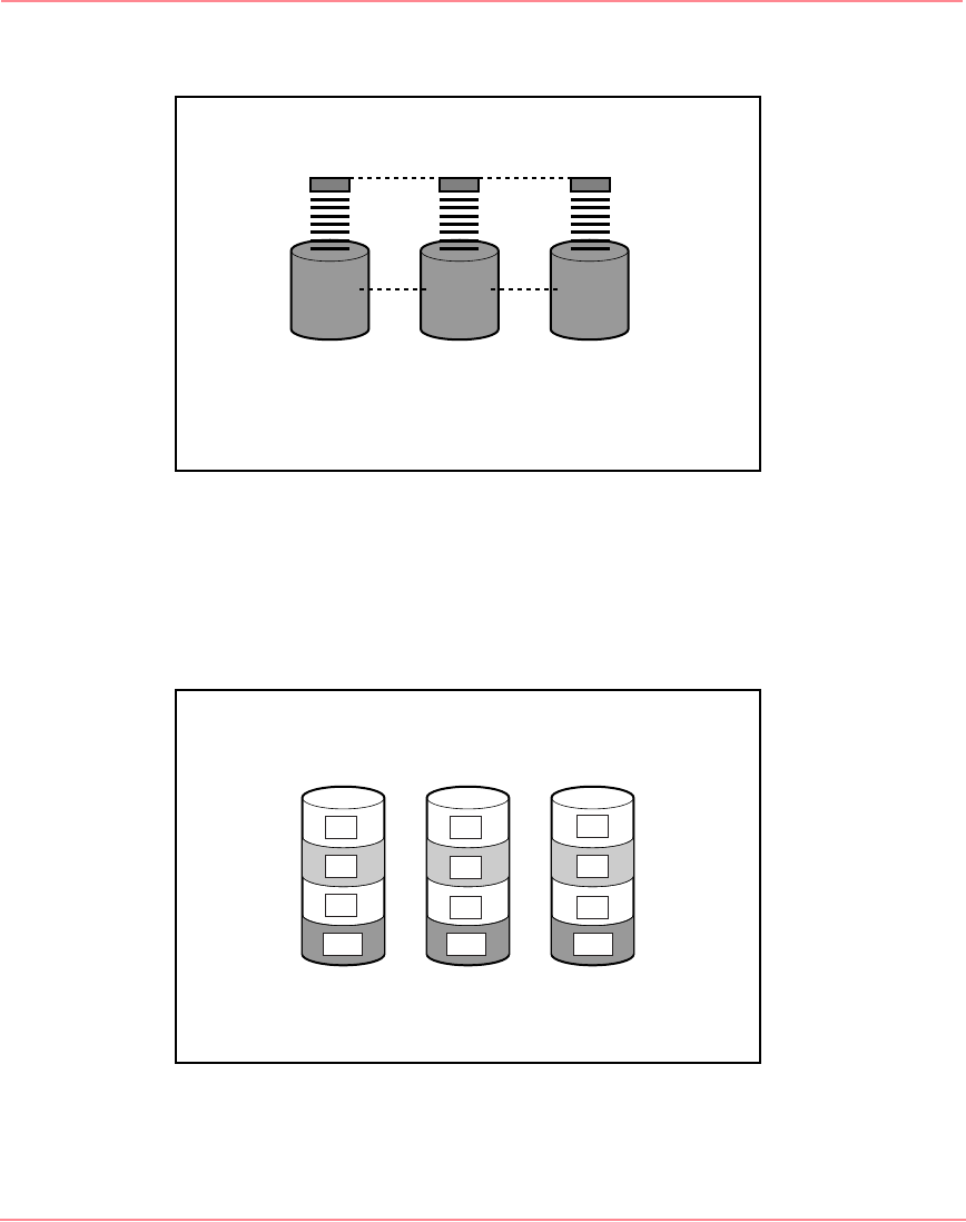
Figure 63: Data striping (S1-S4) of data blocks B1-B12
L1
P1 P2 P3
S1
S2
S3
S4
B1
B4
B7
B2
B5
B8
B11B10 B12
B6
B3
B9
230941-005_MSA1000_UG.book Page 173 Thursday, April 17, 2003 5:53 PM