
Technical data


Installing the c
omponent
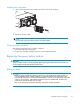
1. Slide the replacement power button module into the bay until it clicks into place.
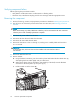
2. Reinstall all
hard drives in slots 10–14.
CAUTION:
To prevent dat
aloss,eachharddrivemustbeinstalledinthesameslotfromwhichis
was removed.
3. Reinstall the MSA in the rack.
4. Reconnect he SCSI, Fibre Channel, and power cables.
5. Apply power to the MSA as instructed in Applying power to the MSA.
Verifying proper operation
After replacing the failed power button module, verify that:
• The module status LED is solid green.
• No new error messages are displayed on the array controller LCD panel.
Replacing the MSA1000 chassis
In the event of a backplane board failure, a new chassis must be ordered. All original component parts
of the MSA can be reinstalled in their respective locations on the new backplane. The parts that will be
removed from the old chassis and then reinstalled in the new chassis include:
• Controllers or controller blank
• Hard drives or blanks
• Power button module
• Fibre Channel I/O modules or interconnect blank
• MSA SAN Switch 2/8 (if installed on previous system)
• MSA Hub 2/3 (if installed on previous system)
• SCSI I/O module
• Power supply/fan assemblies
When fi nished, write the serial number of the original chassis (and MSA SAN Switch 2/8 and MSA
Hub 2/3) on the label of the replacement chassis.
maintenance and service guide
93