
Technical data

Verifying prope
roperation
After replacing
the failed SFP, verify that:
• The 1-Gb and 2-Gb link-status LEDs on the Fibre Channel I/O module cycle through blinking amber
and green and then Off to indicate that the circuitry has recognized a newly installed SFP.
• The status LED on the Fibre Channel I/O module is solid green.
• No new error mes
sages are displayed on the array controller LCD panel.
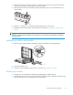
Replacing a power supply/fan assembly
The assembly is hot-pluggable, so it is not necessary to power down the system to replace it.
Before you begin
CAUTION:
• Before removing a component or blanking panel from an operational device, make sure that you
have the replacement part available. Removing a component or blank impacts the airflow and
cooling ability of the device. To avoid possible overheating, insert the new or replacement component
withinoneortwominutes. Iftheinternaltemperatureexceedsacceptablelimits,thedevicemay
overheat and automatically shut down or restart.
• Parts can b
e damaged by electrostatic discharge. Use proper anti-static protection.
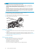
CAUTION:
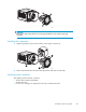
• Replacement power supply assemblies do not include a variable speed fan. You must remove the
operational fan from the defective power supply and install the fan on the new power supply.
• The fan blades rotate at a high speed and do not stop immediately when power is removed from
the MSA. Allow time for the blades to stop rotating. Avoid touching the rotating blades when
removing the fan.
• The fan shell must be handled carefully to avoid breaking it. Do not press on the center section of the
fan shell (circular panel covering the blades). To avoid damaging the fan blades, grasp only the
outer portion of the fan shell. Do not rest the power supply on the fan. Doing so might break the fan.
Verifying component failure
• Check t
he array controller LCD display panel for error messages.
• Verify that the electrical source is delivering power down the AC power cord.
• Verify that the power supply fault LED is flashing amber.
• Verif
y that the power supply Power on/off LED is Off.
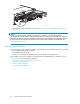
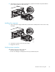
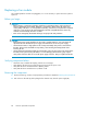
Removing the component
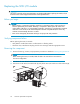
1. Review all warnings, cautions, and preparation procedures as detailed in Warnings and precautions.
2. Disengage the cord lock and disconnect the AC power cord from the failed power supply.
CAUTION:
When removing the left power supply, move the cord lock on the right power supply out of
the way to avoid dislodging the right power supply and causing your system to become
overheated.
86
Customer replaceable components