
Technical data

CAUTION:
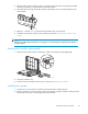
Use appropriate precautions when handling Fibre Channel cables:
• Touching the end of a Fibre Channel cable will either damage the cable or cause performance
problems, including intermittent difficulties accessing the storage.
• Whenever a Fibre Channel cable is not connected, replace the protective covers on the ends of
the cable.
• Make certain that the Fibre Channel cables are installed and supported so that no excess weight is
placed on the connectors. This prevents damage to the connector and cable. Excess cable should
belooselycoiledandtiedoutoftheway,beingcarefulnottocoilthecableinatightloopwitha
bend radius of less than 3 inches (7.62 cm).
1. Review all warnings, cautions, and preparation procedures as detailed in Warnings and precautions.
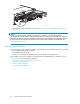
2. Disconnect the cable from the Fibre Channel I/O module.
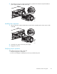
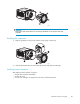
3. While grasping the module handle (1),slidethereleaselatchtotheright.(2).
4. Pullthemoduleoutofthechassis(3).
2
3
1
15569
Installing the component
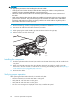
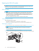
1. Slide the replacement Fibre Channel I/O module into the MSA chassis bay until the module clicks
into place.
2. Either move the SFP transceiver from the old Fibre Channel I/O module or install a new SFP
transceiver in the new module. For instructions on removing and installing an SFP, see Replacing a
2-Gb small form factor pluggable (SFP) transceiver .
3. Reconnect the cables.
Verifying proper operation
After replacing the failed Fibre Channel I/O module verify that:
• TheFibreChannelI/OmodulestatusLEDissolidgreen.
• Verify that the 1-Gb link status is solid green.
• Verify that the 2-Gb link status is solid green.
• No new error messages are displayed on the array controller LCD panel.
84
Customer replaceable components