
Technical data
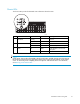


Controller LEDs
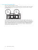
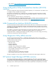
During normal r
untime, the array controller has 18 LEDs that indicate controller activity or malfunction.
1 0 16234567
9 8 17101112131415
15588
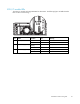
Item Name
Condition
Meaning
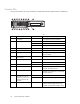
1
Drive failure
On
Aconfi guredharddrivehasfailed.
On
Cache active.
Off
No cache activity.
2
Cache activity
Blinking
Cache tran
sfer pending.
3
SCSI bus 1 activity
On
Activity on the bus.
4
SCSI bus 0 activity
On
Activity on the bus.
5
Logical I/
Oactivity
On
Currently
processing logical requests from
the host a
dapter.
6
Direct Memory Access
(DMA) activity
On
DMA transfers are active.
On
This controller is active.
7
Active/Standby
Off
This con
troller is standby.
8
Heartbeat Blinking
The controller is functioning properly.
9
Fault On (amber) An error message has been sent to the
controller LCD display panel.
10
Redundancy active
On (green)
The two controllers and the two Fibre
Channel I/O modules are in a redundant
mode of operation.
On
The controller is idle.
11–13
Busy status — These
three LEDs are used to
progressively represent the
processing load on the
controller.
Off The controller is operating at full capacity.
14–18
Fibre Channel ID
—
Indicates the 5–bit Arbitrated Loop Physical
Address (ALPA) assigned to this array
controller (not applicable in fabric mode).
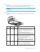
22
System components and LEDs