
Specifications


Operation and Management
41MSA1000 Reference Guide
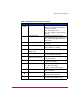
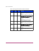
Table 5: MSA1000 Controller Indicator Descriptions
Indicator Function Description
0-2
Busy status These three LEDs are used to
progressively represent the processing
load on the controller.
ON = the controller is idle.
OFF = the controller is operating at full
capacity.
3-7
Fibre Channel ID Indicates the 5-bit Arbitrated Loop
Physical Address (ALPA) assigned to this
array controller (not applicable when in
fabric mode).
8 Idle Heartbeat Indicates the controller is idle and
functioning.
9
Active/Standby ON=Controller is active.
OFF=Controller is in standby.
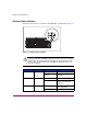
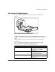
-
Direct Memory Access
(DMA) active
ON = DMA transfers are active.
q
Logical I/O active ON = Currently processing logical
requests from the Host Adapter.
w
SCSI Port A (SCSI Bus 0)
ON = Indicates requests are outstanding
on the first SCSI bus.
e
SCSI Port B (SCSI Bus 1)
ON = Indicates requests are outstanding
on the second SCSI bus.
r
Cache Activity ON = Cache active.
OFF = No cache activity.
Blinking = Cache transfer pending.
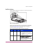
t
Drive failure ON = A configured hard drive has
failed in the array.
@
Redundancy Active Green indicates two controllers are in a
redundant mode of operation.
A
Fault Amber indicates an error message has
been sent to the controller display.