TECHNICAL USER MANUAL FOR: smartCore Express SMA200 Nordstrasse 11/F CH - 4542 Luterbach Tel.: ++41 (0)32 681 58 00 Fax: ++41 (0)32 681 58 01 Email: support@digitallogic.com Homepage: http://www.digitallogic.
DIGITAL-LOGIC AG SMA200 Manual V1.0 For internal use only: File: Path: SMA200_TechManual_V1.0.doc R:\HANDBUCH\smart\SMA200\SMA200_TechManual_V1.0.doc COPYRIGHT 2008 BY DIGITAL-LOGIC AG This publication is protected by copyright and all rights are reserved. No part of this document may be reproduced, transmitted, transcribed or stored in a retrieval system, in any form or by any means, electronic, mechanical, optical, manual, or otherwise, without the prior written permission of DIGITAL-LOGIC AG.
DIGITAL-LOGIC AG SMA200 Manual V1.0 Table of Contents 1. PREFACE .....................................................................................................................................................4 1.1. Trademarks ..................................................................................................................................... 4 1.2. Disclaimer .............................................................................................................................
DIGITAL-LOGIC AG SMA200 Manual V1.0 1. PREFACE The information contained in this manual has been carefully checked and is believed to be accurate; it is subject to change without notice. Product advances mean that some specifications may have changed. DIGITAL-LOGIC AG assumes no responsibility for any inaccuracies, or the consequences thereof, that may appear in this manual.
DIGITAL-LOGIC AG 1.5. SMA200 Manual V1.0 Recycling Information All components within this product fulfill the requirements of the RoHS (Restriction of Hazardous Substances Directive). The product is soldered with a lead free process. 1.6. Technical Support 1. Contact your local DIGITAL-LOGIC Technical Support, in your country. 2. Use the Internet Support Request form at http://support.digitallogic.
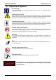
DIGITAL-LOGIC AG 1.8. SMA200 Manual V1.0 Explanation of Symbols CE Conformity This symbol indicates that the product described in this manual is in compliance with all applied CE standards. Caution, Electric Shock! This symbol and title warn of hazards due to electrical shocks (> 60V) when touching products or parts of them. Failure to observe the precautions indicated and/or prescribed by the law may endanger your life/health and/or result in damage to your equipment.
DIGITAL-LOGIC AG 1.9. SMA200 Manual V1.0 Applicable Documents and Standards The following publications are used in conjunction with this manual. When any of the referenced specifications are superseded by an approved revision, that revision shall apply. All documents may be obtained from their respective organizations. Advanced Configuration and Power Interface Specification Revision 2.
DIGITAL-LOGIC AG SMA200 Manual V1.0 Smart Battery Data Specification Revision 1.1, December 11, 1998. www.sbs-forum.org System Management Bus (SMBus) Specification Version 2.0, August 3, 2000 Copyright © 1994, 1995, 1998, 2000 Duracell, Inc., Energizer Power Systems, Inc., Fujitsu, Ltd., Intel Corporation, Linear Technology Inc., Maxim Integrated Products, Mitsubishi Electric Semiconductor Company, PowerSmart, Inc., Toshiba Battery Co. Ltd., Unitrode Corporation, USAR Systems, Inc.
DIGITAL-LOGIC AG SMA200 Manual V1.0 RoHS is often referred to as the "lead-free" directive but it restricts the use of the following substances: Lead Mercury Cadmium Chromium VI PBB and PBDE The maximum allowable concentration of any of the above mentioned substances is 0.1% (except for Cadmium, which is limited to 0.01%) by weight of homogeneous material.
DIGITAL-LOGIC AG SMA200 Manual V1.0 1.12. Swiss Quality 100% Made in Switzerland DIGITAL-LOGIC is a member of "Swiss-Label" This product was not manufactured by employees earning piecework wages This product was manufactured in humane work conditions All employees who worked on this product are paid customary Swiss market wages and are insured ISO 9000:2001 (quality management system) 1.13.
DIGITAL-LOGIC AG SMA200 Manual V1.0 2. OVERVIEW 2.1. Standard Features The smartCoreExpress is an electrical and mechanical definition for a COM or Computer on Module (miniaturized PC system), based on Intel's ATOM chip unit incorporating the major elements of a PC compatible computer. Powerful though low consumption ATOM CPU Soldered DDR2 RAM 512k up to 2GByte Single 220pin connectors (Tyco) for the smartCoreExpress BUS 5x x1 PCI-Express lanes 8x USB V2.
DIGITAL-LOGIC AG 2.2. SMA200 Manual V1.0 Technical Specifications CPU CoreDuo / Celeron M Clock st 1 Level Cache nd 2 Level Cache Technology VCCCore @ 1.6GHz VCCCore @ 1.1GHz VCCCore @ deep sleep CPU BUS AGTL+ Termination FSB Specification Intel Atom 510 1.10GHz with 0.5MB L2-cache Intel Atom 530 1.60GHz with 0.5MB L2-cache 1.1 or 1.6GHz 2x 32kByte 0.54 MByte (on die) 40nm 1.050V 0.844V 0.
DIGITAL-LOGIC AG SMA200 Manual V1.0 Intel US15W PCIe BUS EIDE BUS SATA BUS USB V2.0 APIC SMB FWH LPC Sound IRQ Controller Timers Power Management Specification 2x x1 Lane 1x Ultra P-ATA 100 8 channel USB INTEL I/O APIC V2.0 SMBus controller FirmWare Hub for BIOS devices Serialized BUS (no ISA) used for external SuperI/O AC97 2.
DIGITAL-LOGIC AG Operating Environment Relative Humidity Vibration Shock Operating Temperature Maximum Copper Temperature Storage Temperature SMA200 Manual V1.0 Specification 5-90% non-condensing 5 to 2000 Hz 10 G Standard: t.b.d. (depends on the CPU and the cooling concept) Extended Range: t.b.d.
DIGITAL-LOGIC AG SMA200 Manual V1.0 3. DIMENSIONS & DIAGRAMS 3.1. Block Diagram 1 GB DDR2 RAM FSB Intel Atom Processor Firmware Hub (BIOS) SPI BUS LPC BUS HD Audio / AC link SD/SDIO/MMC 2x PCIe 8x USB PAT SVDO / GMBus (I2C) LVDS, Backlight, DDC Temp.
DIGITAL-LOGIC AG SMA200 Manual V1.0 Design IN with the smartModule Attention! When using an active/passive heatsink that is not from DLAG, be very careful! The maximum depth the screws can go into the product is 3mm or the module will be destroyed! 3.2. Dimensions of the smartCoreExpress Module 65.0mm 58.5mm 3.25 3.25 3.25 View of the bottom side of the smartCoreExpress module. All dimensions with +/-0.1mm tolerance if not otherwise specified. Units = millimeter. 58.0 44.0 50.2 d=1.6 d=1.
DIGITAL-LOGIC AG 3.3. SMA200 Manual V1.0 Connector Placement & Pin Definition on the Carrier Board View of the Top Side (mounting side) of the smartCoreExpress PCB: d=2.2/D=4.5 3.25 3.25 44.0mm smartCoreExpress PCB pad design 58.5mm d=2.2/D=4.5 0.3 1.6 1.6 0.5 0.4 B1 50.2mm B110 1.8 d=1.0 d=1.6 3.6mm A1 A2 A3 ... A110 57.
DIGITAL-LOGIC AG 3.4. SMA200 Manual V1.
DIGITAL-LOGIC AG 3.5. SMA200 Manual V1.0 Dimensions of the Carrier Board Connector SMX-CON8: Standard Height: 5.0mm (Available alternative: 8.0mm) DLAG Part Nr: 807138 AMP/Tyco: 8-6318491-6 (Components placed below the smartModule should total a maximum of 2.0mm.) 3.6. Component Heights between Module and Carrier Board Parts mounted on the back side of the module (in the space between the bottom surface of the module PCB and the carrier board) should have a maximum height of 8.0mm. 6.0mm 5.
DIGITAL-LOGIC AG SMA200 Manual V1.0 4. COM-EXPRESS CONNECTOR DESCRIPTION 4.1. Signal Terminology Descriptions Signal PU PD I/O 3.3V I/O 5V I 3V I 5V I/O 3.3VSB O 3V O 5V P D DDC PCIE SATA LVDS LAN TPM GE-LAN Description Internally implemented pull up resistor Internally implemented pull down resistor Bi-directional signal 3.3V tolerant Bi-directional signal 5V tolerant Input 3.3V tolerant Input 5V tolerant Input 3.3V tolerant, active in standby state Output 3.
DIGITAL-LOGIC AG 4.2. SMA200 Manual V1.
DIGITAL-LOGIC AG SMA200 Manual V1.
DIGITAL-LOGIC AG SMA200 Manual V1.0 5. SIGNAL DESCRIPTIONS OF THE SMARTCOREEXPRESS 5.1. Wire Design for Typical Impedances 5.2.
DIGITAL-LOGIC AG 5.3. SMA200 Manual V1.0 Placing an AC Coupling Capacitor on each PCIe-TX In the smartCoreExpress module, all PCI-TX pairs already include the series AC capacitors.
DIGITAL-LOGIC AG 5.4. SMA200 Manual V1.0 smartCoreExpress Signal Groups 5.4.1. PCI-Express Signal BUS PCIe_Tx [0-4] +/- PCIe PCIe_Rx [0..4] +/- PCIe PCIe_CLK[0..4] +/- PCIe PCIe_REQ#[0..4] PCIe On Module Ext. Ter- Max. Matched Termination mination Length Ohm Length Needed in mm in mm Dif Transmitter 2.5Gbit 100nF Series 200 100 0.2 Out Connected to an Rx pin pair Cap. of the device. Dif Receiver 2.5Gbit Series 200 100 0.2 In Connected to a Tx pin pair Cap. of the device.
DIGITAL-LOGIC AG 5.4.2. Signal SMA200 Manual V1.0 SDVO BUS Type Description SDVO_CTRLCLK SDVO DDC signal SDVO_CTRLDAT SDVO DDC signal SDVO_CLK +/- SDVO Dif Out SDVO_INIT +/- SDVO Dif In SDVO_STALL +/- SDVO Dif In SDVO_TVCLKIN +/- SDVO Dif In SDVO_Red +/- SDVO Dif Out SDVO_Green +/- SDVO Dif Out SDVO_Blue +/- SDVO Dif Out On Module Ext. Ter- Max. Termination mination Length Ohm Needed in mm PU 4.7k to 55 3.3V PU 4.7K to 55 3.
DIGITAL-LOGIC AG 5.4.3. SMA200 Manual V1.0 LVDS On Module Ext. TerTermination mination Needed PU 10k to 3.3V PU 10k to 3.3V Signal BUS Type Description LVDS_DDCCLK LVDS 3.3V DDC signal LVDS_DDCDAT LVDS 3.3V DDC signal LVDS_DATA[0..3] +/- LVDS Dif Out LVDS_CLK +/- LVDS Dif Out LVDS data signal Connected directly to the display. LVDS clock signal Connected directly to the display. LVDS_VDDEN LVDS 3.3V Out LVDS_BKLCTL LVDS 3.3V Out LVDS_BKLEN LVDS 3.
DIGITAL-LOGIC AG 5.4.4. SMA200 Manual V1.0 USB Signal BUS USB_[0..7] +/- USB USB_OC[0..7]# USB On Module Ext. Ter- Max. Termination mination Length Ohm Needed in mm Dif Differential USB data signal 300 100 pair 3.3V USB overcurrent signal PU 10k to 300 55 In 3.3V Type Description If the signals are not used: All these USB signals may be left open. Remarks: EMV/EMI-filters: Use a choke and clamping diode on each signal pair. 28 Matched Length in mm 0.
DIGITAL-LOGIC AG 5.4.5. Signal SMA200 Manual V1.0 Parallel ATA BUS PATA_D[15..0] CMOS PATA_A[0..2] CMOS PATA_IOR#] CMOS PATA_IOW#] CMOS PATA_DACK#] CMOS PATA_CS[3,1] CMOS PATA_REQ CMOS PATA_IORDY CMOS PATA_IRQ CMOS PATA_PCSEL CMOS On Module Terminatio n Series 33 Type Description 5V I/O 5V Out IDE data signals IDE address signal. Connect directly to the PATA device. 5V IDE control signal. Out Connect directly to the PATA-device. 5V IDE control signal.
DIGITAL-LOGIC AG 5.4.6. Signal SMA200 Manual V1.0 LPC BUS BUS Type LPC_FRAME# CMOS 3.3V Out LPC_AD[3..0] CMOS 3.3V I/O LPC_SERIRQ CMOS 3.3V I/O LPC_CLKOUT[0..1] CMOS 3.3V Out Description Connect to the LPC device On Module Ext. Ter- Max. Termination mination Length Ohm Needed in mm 100 55 Connect to the LPC device Connect to the LPC device - PU 10k to 3.3V Connect to the Firmware Series 33 hub or the SuperIO Ohm If the signals are not used: Leave the pins open.
DIGITAL-LOGIC AG 5.4.7. SMA200 Manual V1.0 SMBus Signal BUS SMB_ALERT# CMOS SMB_DATA CMOS SMB_CLOCK CMOS Type 3.3V In 3.3V I/O 3.3V I/O On Module Ext. Ter- Max. Termination mination Length Ohm Needed in mm Connect to the SMB device PU 10k to 200 55 3.3V Connect to the SMB device PU 4.7k to 200 55 open drain 3.3V Connect to the SMB device PU 4.7k to 200 55 open drain 3.3V Description Matched Length in mm - If the signals are not used: The pins can stay open.
DIGITAL-LOGIC AG 5.4.8. SMA200 Manual V1.0 HDA Audio Interface Signal BUS HDA_DOCKEN# CMOS 3.3V Out HAD_RST# CMOS HAD_SYNC CMOS HAD_BITCLK CMOS 3.3V Out 3.3V Out 3.3V Out 3.3V In 3.3V Out 3.3V HAD_SDATAin [1..0] CMOS HAD_SDATAout CMOS HAD_DOCKRST# CMOS Type Description HAD dock enable. This signal controls the external HD audio docking isolation logic. When de-asserted, the switch is in isolate mode. Reset signals for the external codecs. Sample rate at 48kHz to the codecs.
DIGITAL-LOGIC AG 5.4.9. SMA200 Manual V1.0 SD / SDIO Interface Signal BUS Type SD0_CD# CMOS SD0_CLK CMOS 3.3V Out 3.3V Out SD0_CMD# CMOS 3.3V I/O SD_Data [3..0] CMOS 3.3V SD0_LED CMOS SD0_PWR# CMOS 3.3V Out Out SD0_WP CMOS In On Module Ext. TerTermination mination Needed Connect to an SDIO PU 10k to device or card. 3.3V Connects to the pin of Series 47 Series the SD/SDIO device or Ohm 49 Ohm card. Connects to the pin of PU 10k to the SD/SDIO device or 3.3V card.
DIGITAL-LOGIC AG SMA200 Manual V1.0 5.4.10. SPI BUS Signal BUS SPI_MISO CMOS SPI_MOSI CMOS SPI_CLK CMOS SPI_CS# CMOS Type 3.3V In 3.3V Out 3.3V Out 3.3V Out On Module Termination Description Connect to the SPI device. Connect to the SPI device. Connect to the SPI device. f = 17.86 and 31.25MHz Connect to the SPI device. If the signals are not used: Remarks: EMV/EMI filters: Are not needed. 34 Series 33 Ohm Ext. Ter- Max.
DIGITAL-LOGIC AG SMA200 Manual V1.0 5.4.11. SATA Interface (Option) Signal BUS Type SATA_Tx[0..3] SATA SATA_Rx[0..3] SATA Dif Dif On Module Ext. TerTermination mination Needed SATA transmitter pair Series 10nF SATA receiver pair Series 10nF Description Max. Length Ohm in mm 100 100 100 100 Matched Length in mm - If the signals are not used: Unused SATA interfaces may be open. Remarks: The 10nF capacitors 0402 need to be placed directly at the SATA connector. Maximum via count is 2 per signal.
DIGITAL-LOGIC AG SMA200 Manual V1.0 5.4.12. GLAN Signal BUS Type Description GLAN_TX +/- GLAN GLAN_RX +/- GLAN GLAN-CLK +/- GLAN LCI_TXD[2..0] LCI LCI_RXD[2..0] LCI LCI_RST LCI Dif Dif Dif 3.3V Out 3.3V In 3.3V Out On Module Termination Ext. Ter- Max. mination Length Ohm Needed in mm 100nF 250 95 100nF 250 95 33 Ohm 250 50 Matched Length in mm 0.5 0.
DIGITAL-LOGIC AG SMA200 Manual V1.0 5.4.13. CAN / Serial Signal BUS CAN_TX CMOS 3.3V Out CMOS 3.3V In CAN_RX On Module Termination Serial output. Res. Ext. Termination Needed - Serial input. Res. - Type Description If the signals are not used: Unused interfaces may be open. Remarks: EMV/EMI filters: Are not needed. 37 Max.
DIGITAL-LOGIC AG SMA200 Manual V1.0 5.4.14. PM Signal BUS Type WAKE# CMOS 3.3V In WD_OUT CMOS 3.3V Out SUS_S3# CMOS 3.3V Out SUS_S4&5# CMOS 3.3V Out GPIO[3..0] CMOS 3.3V I/O RST_IN# CMOS 3.3V In RST_OUT# CMOS 3.3V Out Power-Good CMOS 3.3V In PS_ON CMOS 3.3V Out PWRBTN# CMOS 3.3V In BIOS_Disable# CMOS 3.3V In A20M# CMOS 3.3V In Speaker CMOS 3.3V Out Description To wakeup the system, this input must be pulled to GND.
DIGITAL-LOGIC AG SMA200 Manual V1.0 5.4.15. Supply Signal BUS Type Description +5Volt PWR In +5V Always VCCRTC PWR PWR In In 5V power supply input. Switched with the sus4signal 5V Always available. RTC supply 3.0-3.6Volt. Connect to a lithium battery, using a 1k series resistor. 39 On Module Ext. TerTermination mination Needed - Max.
DIGITAL-LOGIC AG 6. SMA200 Manual V1.0 SMARTCORE-EXPRESS CONNECTOR SPECIFICATIONS The connector type is equal to the COMexpress connector. This is a 220pin, surface-mounted connector with 0.5mm pitch. Parameter Material Electrical Mechanical Condition Contact Housing Current Voltage Termination Resistance Insulation Resistance Mating Cycles Connector Mating Force Connector Un-mating Force Pitch Number of pins Temperature rating Specification Copper alloy Thermoplast molded compound LCP 0.
DIGITAL-LOGIC AG 7. SMA200 Manual V1.0 SMARTCORE-EXPRESS VERSUS COMEXPRESS The smartCoreExpress supports small footprints and especially mobile applications. It is powered by the modern Intel Atom CPU technology. To select the correct module, this chapter compares the different PCIe-based module concepts. All concepts allow minimum (required) and maximum (optional) features. The following table summarizes the features of all PCIe COMs.
DIGITAL-LOGIC AG SMA200 Manual V1.0 8. INDEX A P AC Coupling Capacitor............................................... 24 B Photo of the Top Side of the PCB .............................. 18 Pin Definition .............................................................. 17 Power Management ................................................... 13 Power Supply ............................................................. 13 Block Diagram............................................................ 15 BUS....