
Technical data


System Management Features
4.13 Volume Shadowing for OpenVMS
4.13.2.1 How to Use the New DISMOUNT and SET Command Qualifiers
The diagram in this section depicts a typical multiple-site cluster using Fibre
Channel. It is used to illustrate the steps which must be taken to manually
recover one site when the site-to-site storage interconnect fails. Note that with
current Fibre Channel support, neither site can use the MSCP server to regain a
path to the DGA devices.
To prevent the shadowing driver from automatically recovering shadow sets from
connection-related failures, three steps must be taken prior to any failure:
1. Every device that is a member of a multiple-site shadow set must have its
member_timeout setting raised to a high value, using the following command:
$ SET DEVICE /MEMBER_TIMEOUT= x ddcu:
This command will override the SHADOW_MBR_TMO value, which would
normally be used for a shadow set member. A value for x of 259200 would be
a seventy-two hour wait time.
2. Every shadow set that spans multiple sites must have its mount verification
timeout setting raised to a very high value, higher than the MEMBER_
TIMEOUT settings for each member of the shadow set.
Use the following command to increase the mount verification timeout setting
for the shadow set:
$ SET DEVICE /MVTIMEOUT = y DSAnnnn
The y value of this command should always be greater than the x value of the
$ SET DEVICE/MEMBER_TIMEOUT= x ddcu:
.
The
$ SET DEVICE /MVTIMEOUT = y
command will override the MVTIMEOUT
value, which would normally be used for the shadow set. A value for y of
262800 would be a seventy-three hour wait.
3. Every shadow set and every shadow set member must have a site qualifier.
As already noted, a site qualifier will ensure that the read cost is correctly set.
The other critical factor is three-member shadow sets. When they are being
used, the site qualifier will ensure that the master member of the shadow set
will be properly maintained.
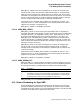
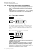
In the following diagram, shadow set DSA42 is made up of $1$DGA1000 and
$1$DGA2000
<><><><><><><><><><><> LAN <><><><><><><><><><><>
Site A Site B
||
F.C. SWITCH <><><><> XYZZY <><><><> F.C. SWITCH
||
HSG80 <><> HSG80 HSG80 <><> HSG80
||
$1$DGA1000 --------- DSA42 --------- $1$DGA2000
This diagram illustrates that systems at Site A or Site B have direct access to all
devices at both sites via Fibre Channel connections. XYZZY is a theoretical point
between the two sites. If the Fibre Channel connection were to break at this
point, each site could access different ‘‘local’’ members of DSA42 without error.
For the purpose of this example, Site A will be the sole site chosen to retain
access to the shadow set.
The following actions must be taken to recover the shadow set at Site A.
4–24 System Management Features