
User`s guide
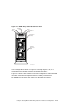
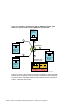
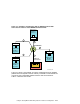
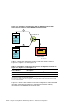
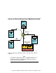
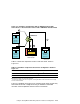
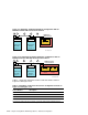
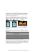
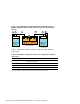

Figure 2–11 shows an externally terminated TruCluster configuration
using an RA3000. In this configuration, because the Host 0 I/O module is
daisy-chained to Host 1 I/O module, dual HSZ22 controllers could use
active/active or active/passive failover.
Figure 2–11: Externally Terminated TruCluster Configuration with an
RA3000 Controller Shelf with Active/Active or Active/Passive Failover
AlphaServer
Member
KZPBA-CB
System 2
AlphaServer
Member
KZPBA-CB
System 1
T
1
2
3
RAID Array 3000
Controller Shelf
Host 0 I/O
Module
Host 1 I/O
Module
Host
In
Host
Out
Host
In
Host
Out
4
2
5
ZK-1482U-AI
T
Table 2–8 shows the components used to create the cluster shown in
Figure 2–11.
Table 2–8: Hardware Components Used in the Configuration Shown in
Figure 2–11
Callout Number Description
1 H879-AA terminator
2 BN21W-0B Y cable
3 BN21K (BN21L or BN31G) HD68 cable
a
4
BN38C HD68 to VHDCI cable
a
5 BN37A-0E 0.5-meter VHDCI cable
a
The maximum length of the SCSI bus segment, including the combined length of BN21K (BN21L or
BN31G) and BN38C cables and internal device length, must not exceed 25 meters.
Figure 2–12 shows an externally terminated TruCluster configuration with
a RA3000 in the middle of the bus. In this configuration, because Host 0
I/O module is daisy-chained to Host 1 I/O module, dual HSZ22 controllers
could use active/active or active/passive failover.
Using the StorageWorks RAID Array 3000 in a TruCluster Configuration 2–27