
User guide

Hardware options installation 78
o
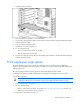
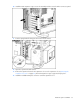
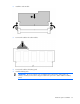
Install the server in the rack.
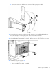
24. Connect any external cables to the PCI-X expansion boards.
25. Power up the server (on page 25).
Battery-backed write cache option
The server supports multiple memory modules and RAID levels:
• 256 MB supports RAID 0, 1, 10
• 512 MB supports RAID 0, 1, 5, and 10
CAUTION: To prevent a server malfunction or damage to the equipment, do not add or
remove the battery pack while an array capacity expansion, RAID level migration, or stripe
size migration is in progress.
IMPORTANT: The battery pack might have a low charge when installed. In this case, a POST
error message is displayed when the server is powered up, indicating that the battery pack is
temporarily disabled. No action is necessary on your part. The internal circuitry automatically
recharges the batteries and enables the battery pack. This process might take up to four
hours. During this time, the cache module functions properly, but without the performance
advantage of the battery pack.
NOTE: The data protection and the time limit also apply if a power outage occurs. When
power is restored to the system, an initialization process writes the preserved data to the hard
drives.
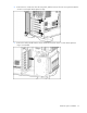
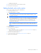
To install the component:
1. Power down the server (on page 25).
2. Do one of the following:
o Open or remove the tower bezel, as needed ("Open or remove the tower bezel" on page 26).
o Extend the server from the rack (on page 25).
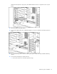
3. Remove the access panel (on page 27).
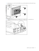
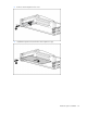
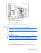
4. Locate the cache module connector ("System board components" on page 11).
5. Open the cache module latches.