
User guide
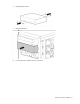
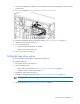
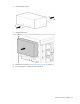
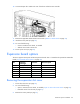
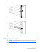
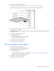
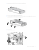
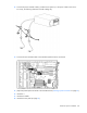
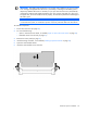
Table Of Contents
- HP ProLiant ML330 G6 Server User Guide
- Abstract
- Notice
- Contents
- Component identification
- Operations
- Setup
- Hardware options installation
- Introduction
- Processor option
- Memory options
- Redundant hot-plug power supply option
- Redundant fan assembly option
- SAS or SATA hard drive option
- Expansion hard drive cage option (hot-plug)
- Expansion hard drive cage option (non-hot-plug)
- Removable media devices
- Expansion board options
- PCI-X extender board option
- Storage controller option
- Battery-backed write cache battery pack option
- FBWC module and capacitor pack option
- SAS controller option
- Dedicated iLO 2 port module option
- HP Trusted Platform Module option
- Cabling
- Configuration and utilities
- Troubleshooting
- Battery replacement
- Regulatory compliance notices
- Regulatory compliance identification numbers
- Federal Communications Commission notice
- Declaration of conformity for products marked with the FCC logo, United States only
- Modifications
- Cables
- Canadian notice (Avis Canadien)
- European Union regulatory notice
- Disposal of waste equipment by users in private households in the European Union
- Japanese notice
- BSMI notice
- Korean notice
- Chinese notice
- Laser compliance
- Battery replacement notice
- Taiwan battery recycling notice
- Power cord statement for Japan
- Electrostatic discharge
- Specifications
- Technical support
- Acronyms and abbreviations
- Index
Hardware options installation 69
19. Do one of the following:
o Close or install the tower bezel, as needed.
o Slide the server back into the rack.
20. Connect all power cords to the server.
21. Connect power cords to the power source.
22. Power up the server (on page 20).
Storage controller option
IMPORTANT: For additional installation and configuration information, refer to the
documentation that ships with the option.
To install the component:
1. Power down the server (on page 20).
2. Do one of the following:
o Open or remove the tower bezel, as needed ("Open or remove the tower bezel" on page 20).
o Extend the server from the rack (on page 21).
3. Remove the access panel (on page 21).
4. Remove the air baffle (on page 22).
5. Install the storage controller ("Installing expansion boards" on page 65).
6. Connect the mini-SAS to mini-SAS cable, provided in the mini-SAS to mini-SAS cable option kit, to the
hard drive backplane and to the storage controller.
7. Install the air baffle.
8. Install the access panel (on page 22).
9. Do one of the following:
o Close or install the tower bezel, as needed.
o Slide the server back into the rack.
10. Power up the server (on page 20).
Battery-backed write cache battery pack option
CAUTION: To prevent a server malfunction or damage to the equipment, do not add or remove
the battery pack while an array capacity expansion, RAID level migration, or stripe size migration
is in progress.
CAUTION: After the server is powered down, wait 15 seconds and then check the amber LED
before unplugging the cable from the cache module. If the amber LED blinks after 15 seconds, do
not remove the cable from the cache module. The cache module is backing up data, and data is
lost if the cable is detached.