
User guide
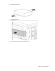
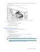
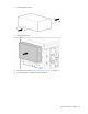
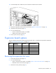
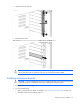
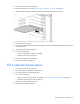
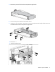
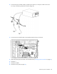
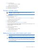
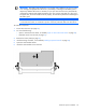
Table Of Contents
- HP ProLiant ML330 G6 Server User Guide
- Abstract
- Notice
- Contents
- Component identification
- Operations
- Setup
- Hardware options installation
- Introduction
- Processor option
- Memory options
- Redundant hot-plug power supply option
- Redundant fan assembly option
- SAS or SATA hard drive option
- Expansion hard drive cage option (hot-plug)
- Expansion hard drive cage option (non-hot-plug)
- Removable media devices
- Expansion board options
- PCI-X extender board option
- Storage controller option
- Battery-backed write cache battery pack option
- FBWC module and capacitor pack option
- SAS controller option
- Dedicated iLO 2 port module option
- HP Trusted Platform Module option
- Cabling
- Configuration and utilities
- Troubleshooting
- Battery replacement
- Regulatory compliance notices
- Regulatory compliance identification numbers
- Federal Communications Commission notice
- Declaration of conformity for products marked with the FCC logo, United States only
- Modifications
- Cables
- Canadian notice (Avis Canadien)
- European Union regulatory notice
- Disposal of waste equipment by users in private households in the European Union
- Japanese notice
- BSMI notice
- Korean notice
- Chinese notice
- Laser compliance
- Battery replacement notice
- Taiwan battery recycling notice
- Power cord statement for Japan
- Electrostatic discharge
- Specifications
- Technical support
- Acronyms and abbreviations
- Index
Hardware options installation 62
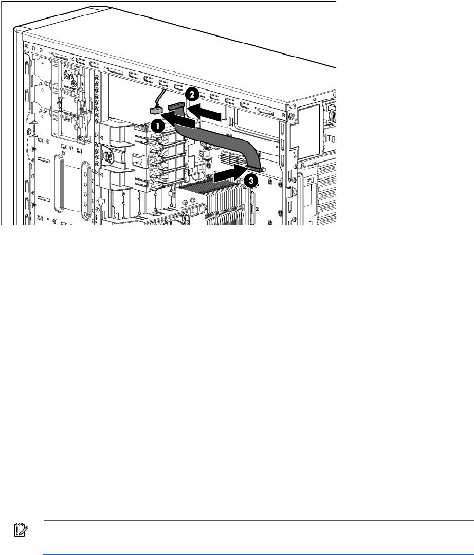
9. Connect the USB tape drive cable to the rear of the drive and to the USB tape drive connector on the
system board.
10. Remove the applicable bezel blank from the bezel ("Remove a bezel blank" on page 24).
11. Install the access panel (on page 22).
12. Do one of the following:
o Close or install the tower bezel, as needed.
o Slide the server back into the rack.
13. Power up the server (on page 20).
Full-height tape drive option
For clarity, the following illustrations include option cabling only.
To install the component:
1. Power down the server (on page 20).
2. Do one of the following:
o Unlock and remove the bezel ("Open or remove the tower bezel" on page 20).
o Extend the server from the rack (on page 21).
3. Remove the access panel (on page 21).
4. Remove the applicable media bay blanks ("Remove the media bay blank" on page 23).
IMPORTANT: For correct cabling, install the full-height tape drive in the top two slots.
5. Identify the guide screws ("Identifying guide screws" on page 58).