
User guide
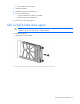
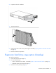
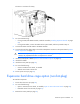
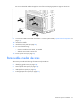
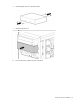
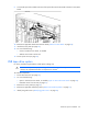
Table Of Contents
- HP ProLiant ML330 G6 Server User Guide
- Abstract
- Notice
- Contents
- Component identification
- Operations
- Setup
- Hardware options installation
- Introduction
- Processor option
- Memory options
- Redundant hot-plug power supply option
- Redundant fan assembly option
- SAS or SATA hard drive option
- Expansion hard drive cage option (hot-plug)
- Expansion hard drive cage option (non-hot-plug)
- Removable media devices
- Expansion board options
- PCI-X extender board option
- Storage controller option
- Battery-backed write cache battery pack option
- FBWC module and capacitor pack option
- SAS controller option
- Dedicated iLO 2 port module option
- HP Trusted Platform Module option
- Cabling
- Configuration and utilities
- Troubleshooting
- Battery replacement
- Regulatory compliance notices
- Regulatory compliance identification numbers
- Federal Communications Commission notice
- Declaration of conformity for products marked with the FCC logo, United States only
- Modifications
- Cables
- Canadian notice (Avis Canadien)
- European Union regulatory notice
- Disposal of waste equipment by users in private households in the European Union
- Japanese notice
- BSMI notice
- Korean notice
- Chinese notice
- Laser compliance
- Battery replacement notice
- Taiwan battery recycling notice
- Power cord statement for Japan
- Electrostatic discharge
- Specifications
- Technical support
- Acronyms and abbreviations
- Index
Hardware options installation 58
Identifying guide screws
When installing drives in the removable media bay, guide screws must be installed so that the drives align
correctly in the drive cage. HP has provided extra guide screws, located behind the side access panel.
Depending on the option, use 5.25 M3 metric screws or HD 6-32 shipping screws. The metric screws
supplied by HP are black.
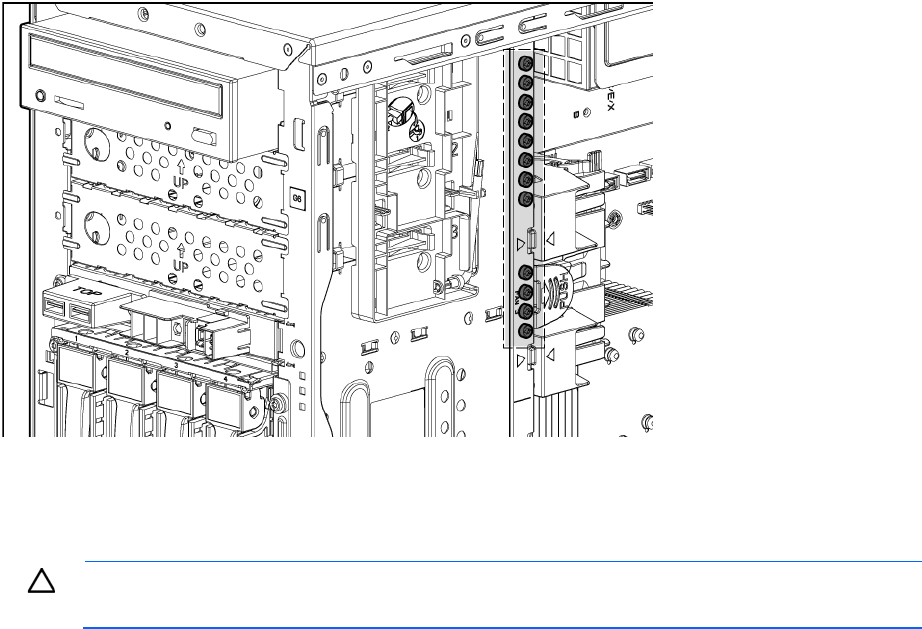
SATA optical drive option
For clarity, the following illustrations include option cabling only.
CAUTION: To prevent improper cooling and thermal damage, do not operate the server unless
all bays are populated with either a component or a blank.
To install the component:
1. Power down the server (on page 20).
2. Do one of the following:
o Open or remove the tower bezel, as needed ("Open or remove the tower bezel" on page 20).
o Extend the server from the rack (on page 21).
3. Remove the access panel (on page 21).
4. Remove the applicable media bay blank ("Remove the media bay blank" on page 23).
5. Identify the guide screws ("Identifying guide screws" on page 58).