
User guide
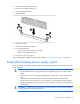
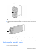
Table Of Contents
- HP ProLiant ML330 G6 Server User Guide
- Abstract
- Notice
- Contents
- Component identification
- Operations
- Setup
- Hardware options installation
- Introduction
- Processor option
- Memory options
- Redundant hot-plug power supply option
- Redundant fan assembly option
- SAS or SATA hard drive option
- Expansion hard drive cage option (hot-plug)
- Expansion hard drive cage option (non-hot-plug)
- Removable media devices
- Expansion board options
- PCI-X extender board option
- Storage controller option
- Battery-backed write cache battery pack option
- FBWC module and capacitor pack option
- SAS controller option
- Dedicated iLO 2 port module option
- HP Trusted Platform Module option
- Cabling
- Configuration and utilities
- Troubleshooting
- Battery replacement
- Regulatory compliance notices
- Regulatory compliance identification numbers
- Federal Communications Commission notice
- Declaration of conformity for products marked with the FCC logo, United States only
- Modifications
- Cables
- Canadian notice (Avis Canadien)
- European Union regulatory notice
- Disposal of waste equipment by users in private households in the European Union
- Japanese notice
- BSMI notice
- Korean notice
- Chinese notice
- Laser compliance
- Battery replacement notice
- Taiwan battery recycling notice
- Power cord statement for Japan
- Electrostatic discharge
- Specifications
- Technical support
- Acronyms and abbreviations
- Index
Hardware options installation 45
• In multi-processor configurations, each processor must have a valid Lockstep Memory configuration.
• In multi-processor configurations, each processor may have a different valid Lockstep Memory
configuration.
Single-processor Lockstep population order
For Lockstep memory mode configurations with a single processor, populate the DIMM slots in the following
order:
• RDIMM
o First: A and B
o Next: D and E
o Last: G and H
o Do not populate slots C, F, or I.
• UDIMM
o First: A and B
o Last: D and E
o Do not populate slots C, F, G, H, or I.
After installing the DIMMs, use RBSU to configure the system for Lockstep memory support ("Configuring
lockstep memory" on page 88).
Multi-processor Lockstep population order
For Lockstep memory mode configurations with multiple processors, populate the DIMM slots for each
processor in the following order:
• RDIMM
o First: A and B
o Next: D and E
o Last: G and H
o Do not populate slots C, F, or I.
• UDIMM
o First: A and B
o Last: D and E
o Do not populate slots C, F, G, H, or I.
After installing the DIMMs, use RBSU to configure the system for Lockstep memory support ("Configuring
lockstep memory" on page 88).
Mirrored Memory population guidelines
For Mirrored Memory mode configurations, observe the following guidelines:
• Observe the general DIMM slot population guidelines (on page 43).
• Always install DIMMs in channels 1 and 2 for each installed processor.
• Do not install DIMMs in channel 3 for any processor.