
User guide
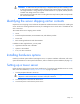
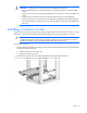
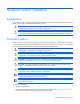
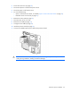
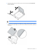
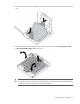
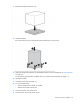
Table Of Contents
- HP ProLiant ML330 G6 Server User Guide
- Abstract
- Notice
- Contents
- Component identification
- Operations
- Setup
- Hardware options installation
- Introduction
- Processor option
- Memory options
- Redundant hot-plug power supply option
- Redundant fan assembly option
- SAS or SATA hard drive option
- Expansion hard drive cage option (hot-plug)
- Expansion hard drive cage option (non-hot-plug)
- Removable media devices
- Expansion board options
- PCI-X extender board option
- Storage controller option
- Battery-backed write cache battery pack option
- FBWC module and capacitor pack option
- SAS controller option
- Dedicated iLO 2 port module option
- HP Trusted Platform Module option
- Cabling
- Configuration and utilities
- Troubleshooting
- Battery replacement
- Regulatory compliance notices
- Regulatory compliance identification numbers
- Federal Communications Commission notice
- Declaration of conformity for products marked with the FCC logo, United States only
- Modifications
- Cables
- Canadian notice (Avis Canadien)
- European Union regulatory notice
- Disposal of waste equipment by users in private households in the European Union
- Japanese notice
- BSMI notice
- Korean notice
- Chinese notice
- Laser compliance
- Battery replacement notice
- Taiwan battery recycling notice
- Power cord statement for Japan
- Electrostatic discharge
- Specifications
- Technical support
- Acronyms and abbreviations
- Index
Setup 32
WARNING: To reduce the risk of electric shock or damage to the equipment:
• Do not disable the power cord grounding plug. The grounding plug is an important safety
feature.
•
Plug the power cord into a grounded (earthed) electrical outlet that is easily accessible at all
times.
• Unplug the power cord from the power supply to disconnect power to the equipment.
• Do not route the power cord where it can be walked on or pinched by items placed against it.
Pay particular attention to the plug, electrical outlet, and the point where the cord extends from
the server.
Installing a server in a rack
The procedure to install the tray in the rack is similar to the procedures to install a server in a rack. For more
information, see the 2U Quick Deploy Rail System Installation Instructions that shipped in the rail kit.
CAUTION: To avoid damage to the equipment, be sure that the rack rails are installed in a
predetermined location on the rack so that airflow clearance issues are resolved. For airflow
clearance information, refer to the documentation that ships with the server.
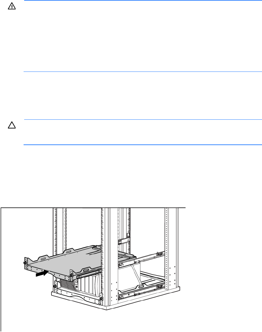
To install the component:
1. See the "Installing the Product into a Rack" section of the 2U Quick Deploy Rack Rail System Installation
Instructions to do the following:
a. Install the component rails on the tray.
b. Install the rack rails in the rack.
2. Install the tray onto the rack rails, and then partially slide the assembly into the rack.