HP ProLiant ML330 G6 Server User Guide Abstract This document is for the person who installs, administers, and troubleshoots servers and storage systems. HP assumes you are qualified in the servicing of computer equipment and trained in recognizing hazards in products with hazardous energy levels.
© Copyright 2009, 2011 Hewlett-Packard Development Company, L.P. The information contained herein is subject to change without notice. The only warranties for HP products and services are set forth in the express warranty statements accompanying such products and services. Nothing herein should be construed as constituting an additional warranty. HP shall not be liable for technical or editorial errors or omissions contained herein. Microsoft, Windows, and Windows Server are U.S.
Contents Component identification ............................................................................................................... 7 Front panel components ............................................................................................................................. 7 Front panel LEDs and buttons ...................................................................................................................... 8 Rear panel components .........................................
Introduction ............................................................................................................................................ 35 Processor option...................................................................................................................................... 35 Memory options ...................................................................................................................................... 41 Memory subsystem architecture ..................
Redundant ROM support ................................................................................................................ 90 USB support .................................................................................................................................. 91 Diagnostic tools ...................................................................................................................................... 91 HP Insight Diagnostics ..................................................
Power cord statement for Japan............................................................................................................... 119 Electrostatic discharge ............................................................................................................... 120 Preventing electrostatic discharge ............................................................................................................ 120 Grounding methods to prevent electrostatic discharge ........................
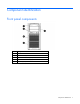
Component identification Front panel components Item Description 1 Optical drive 2 USB connectors (2) 3 Standard hard drive bays (4) 4 Expansion hard drive bays (4) 5 Media bays (2) Component identification 7
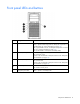
Front panel LEDs and buttons Item Description Status 1 System health LED Green = System health is normal. Amber = System health is degraded. To identify the component in a degraded state, see "System board LEDs (on page 13)." Red = System health is critical. To identify the component in a critical state, see "System board LEDs (on page 13)." Off = System health is normal (when in standby mode). 2 NIC 1 link/activity LED Green or flashing green = Activity exists. Off = No activity exists.
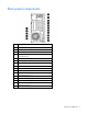
Rear panel components Item Description 1 Dedicated iLO 2 management port (optional) 2 Serial connector 3 10/100/1000 NIC 2 connector 4 10/100/1000 NIC 1 connector/shared iLO 2 management port 5 Mouse connector 6 Power supply 1 7 Power supply blank 8 Slot 1 PCI-X* 9 Slot 2 PCI-X* 10 Slot 3 PCIe1 x8 (1) 11 Slot 4 PCIe2 x16 (16, 8, 4, 2, 1) 12 Slot 5 PCIe2 x8 (4, 2, 1) 13 Slot 6 PCIe2 x8 (4, 2, 1) 14 Video connector 15 USB connectors (2) 16 Keyboard connector Component identi
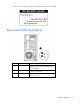
*Slots 1 and 2 are available only when an optional PCI-X extender board is installed. Rear panel LEDs and buttons Item Description Status 1 UID button/LED Blue = Activated Flashing = System is being managed remotely. Off = Deactivated 2 NIC/iLO 2 activity Green or flashing green = Activity exists. Off = No activity exists. 3 NIC/iLO 2 link Green = Link exists. Off = No link exists.
System board components For this server, some system board slots and connectors are reserved.
Item Description 23 System power connector 24 Fan 1 connector 25 Fan 1.5 or 2 connector 26 Fan 3 connector 27 Reserved 28 Processor socket 1 (populated) 29 Battery 30 Reserved 31 Power connector 32 Front USB connector * The server supports one optical drive that can be connected to either SATA connector 5 or SATA connector 6. System maintenance switch Position Default Function S1 Off Off = iLO 2 security is enabled. On = iLO 2 security is disabled.
NMI functionality An NMI crash dump enables administrators to create crash dump files when a system is hung and not responding to traditional debug mechanisms. Crash dump log analysis is an essential part of diagnosing reliability problems, such as hangs in operating systems, device drivers, and applications. Many crashes freeze a system, and the only available action for administrators is to cycle the system power.
Item LED description Status Off = Normal 5 Fan 1 failure Amber = Fan has failed or is missing. Off = Normal 6 Fan 1.5 or 2 failure Amber = Fan has failed or is missing. Off = Normal 7 DIMM failure (1-9) Amber = DIMM has failed or is missing. Off = Normal 8 Fan 3 failure Amber = Fan has failed or is missing. Off = Normal System LEDs and internal health LED combinations When the internal health LED on the front panel illuminates either amber or red, the server is experiencing a health event.
System LED and Color Internal Health LED Color Power supply (amber) Red Status One or more of the following conditions may exist: • • Amber There is no AC power. The power supply has failed. There is a power supply mismatch at POST. DIMM slots DIMM slots are numbered sequentially (1 through 9) for each processor. The supported AMP modes use the letter assignments for population guidelines. DIMM identification IMPORTANT: This server does not support mixing RDIMMs and UDIMMs.
The memory subsystem may be populated with either RDIMMs or UDIMMs, but mixing the two types is not supported. To determine DIMM characteristics, use the label attached to the DIMM and the following illustration and table.
SAS and SATA device numbers • Standard configuration • Optional configuration with hard drive expansion cage Component identification 17
Hot-plug SATA or SAS hard drive LEDs Item LED description Status 1 Fault/UID status Amber = Drive failure Flashing amber = Fault-process activity Blue = Unit identification is active Off = No fault-process activity 2 Online/Activity status Green = Drive activity Flashing green = High activity on the drive or drive is being configured as part of an array Off = No drive activity The online/activity status LED will not illuminate if using SATA drives connected to the embedded storage device.
Fan locations • Standard fan configuration • Redundant fan configuration Component identification 19
Operations Power up the server To power up the server, press the Power On/Standby button. Power down the server WARNING: To reduce the risk of personal injury, electric shock, or damage to the equipment, remove the power cord to remove power from the server. The front panel Power On/Standby button does not completely shut off system power. Portions of the power supply and some internal circuitry remain active until AC power is removed.
2. Using the key provided with the server, unlock the bezel. 3. Remove the bezel, as needed. Extend the server from the rack NOTE: If the optional cable management arm option is installed, you can extend the server without powering down the server or disconnecting peripheral cables and power cords. These steps are only necessary with the standard cable management solution. 1. Power down the server (on page 20). 2. Disconnect all peripheral cables and power cords from the server rear panel. 3.
3. Loosen the access panel screws. 4. Slide the access panel back about 1.5 cm (0.5 in). 5. Lift and remove the access panel. CAUTION: For proper cooling, do not operate the server without the access panel, baffles, expansion slot covers, hard drives, or blanks installed. Install the access panel 1. Place the access panel on top of the server, allowing it to extend past the rear of the server approximately 1.5 cm (0.5 in). 2.
o Open or remove the tower bezel, as needed ("Open or remove the tower bezel" on page 20). o Extend the server from the rack (on page 21). 3. Remove the access panel (on page 21). 4. Remove the air baffle (on page 22). 5. Press and hold the release button. 6. Remove the partition. Remove the media bay blank 1. Power down the server (on page 20). 2. Open or remove the tower bezel, as needed ("Open or remove the tower bezel" on page 20).
CAUTION: Always populate each media bay with either a device or a blank. Proper airflow can only be maintained when the bays are populated. Unpopulated drive bays can lead to improper cooling and thermal damage. 3. Remove the media bay blank. Remove a bezel blank 1. Power down the server (on page 20). 2. Remove the front bezel ("Open or remove the tower bezel" on page 20). 3. Remove a bezel blank. Remove the processor board 1. Power down the server (on page 20). 2.
3. Remove the access panel (on page 21). 4. Place the tower server on its side. 5. Remove the air baffle (on page 22). 6. Disconnect the power cable from the processor board. 7. Using a T-15 Torx screwdriver, remove the screws securing the processor board. 8. Remove the processor board. 9. Using the wrench provided in the kit, remove the mezzanine support stand-offs. 10. Remove the metal plate. Install the processor board 1. Power down the server (on page 20). 2.
o Open or remove the tower bezel, as needed ("Open or remove the tower bezel" on page 20). o Extend the server from the rack (on page 21). 3. Remove the access panel (on page 21). 4. Place the tower server on its side. 5. Remove the air baffle (on page 22). 6. Using a T-15 Torx screwdriver, remove the seven screws on the system board. Save the screws. 7. Using the wrench provided in the kit, install the seven mezzanine base stand-offs. 8.
9. Using the wrench from the kit, install the mezzanine support stand-offs. 10. Install the processor board. 11. Using the screws removed from the system board, secure the processor board.
Setup Optional installation services Delivered by experienced, certified engineers, HP Care Pack services help you keep your servers up and running with support packages tailored specifically for HP ProLiant systems. HP Care Packs let you integrate both hardware and software support into a single package. A number of service level options are available to meet your needs.
• Leave a minimum clearance of 121.9 cm (48 in) from the back of the rack to the back of another rack or row of racks. HP servers draw in cool air through the front door and expel warm air through the rear door. Therefore, the front and rear rack doors must be adequately ventilated to allow ambient room air to enter the cabinet, and the rear door must be adequately ventilated to allow the warm air to escape from the cabinet.
(code for Protection of Electronic Computer/Data Processing Equipment). For electrical power ratings on options, refer to the product rating label or the user documentation supplied with that option. WARNING: To reduce the risk of personal injury, fire, or damage to the equipment, do not overload the AC supply branch circuit that provides power to the rack. Consult the electrical authority having jurisdiction over wiring and installation requirements of your facility.
WARNING: To reduce the risk of personal injury or equipment damage when unloading a rack: • At least two people are needed to safely unload the rack from the pallet. An empty 42U rack can weigh as much as 115 kg (253 lb), can stand more than 2.1 m (7 ft) tall, and may become unstable when being moved on its casters. • Never stand in front of the rack when it is rolling down the ramp from the pallet. Always handle the rack from both sides.
WARNING: To reduce the risk of electric shock or damage to the equipment: • Do not disable the power cord grounding plug. The grounding plug is an important safety feature. • Plug the power cord into a grounded (earthed) electrical outlet that is easily accessible at all times. • Unplug the power cord from the power supply to disconnect power to the equipment. • Do not route the power cord where it can be walked on or pinched by items placed against it.
3. Attach the straps to the tray. 4. Place the server on the tray, and then secure the server to the tray. CAUTION: To prevent damage to equipment, do not place the monitor on a rack-mounted server. The rack enabling kit supports only the server. 5. Slide the tray fully into the rack, and then tighten the thumbscrews.
6. Slide the locking bracket forward, and then tighten the thumbscrews. Installing the operating system To operate properly, the server must have a supported operating system. For the latest information on supported operating systems, refer to the HP website (http://www.hp.com/go/supportos). Two methods are available to install an operating system on the server: • SmartStart assisted installation—Insert the SmartStart CD into the CD-ROM drive and reboot the server.
Hardware options installation Introduction If more than one option is being installed, read the installation instructions for all the hardware options and identify similar steps to streamline the installation process. WARNING: To reduce the risk of personal injury from hot surfaces, allow the drives and the internal system components to cool before touching them. CAUTION: To prevent damage to electrical components, properly ground the server before beginning any installation procedure.
2. Power down the server (on page 20). 3. Disconnect all power cords from the power source. 4. Disconnect power cords from the server. 5. Do one of the following: o Open or remove the tower bezel, as needed ("Open or remove the tower bezel" on page 20). o Extend the server from the rack (on page 21). 6. Remove the access panel (on page 21). 7. Place the tower server on its side. 8. Remove the air baffle (on page 22). 9. Configure the air baffle (on page 22). 10.
12. Open the processor locking lever and the processor socket retaining bracket. Do not remove the processor socket cover. IMPORTANT: Be sure the processor remains inside the processor installation tool. 13. If the processor has separated from the installation tool, carefully re-insert the processor in the tool. Handle the processor by the edges only, and do not touch the bottom of the processor, especially the contact area.
14. Align the processor installation tool with the socket, and then install the processor. THE PINS ON THE SYSTEM BOARD ARE VERY FRAGILE AND EASILY DAMAGED. CAUTION: THE PINS ON THE SYSTEM BOARD ARE VERY FRAGILE AND EASILY DAMAGED. To avoid damage to the system board: • Never install or remove a processor without using the processor installation tool. • Do not touch the processor socket contacts. • Do not tilt or slide the processor when lowering the processor into the socket.
15. Press the tabs on the processor installation tool to separate it from the processor, and then remove the tool. 16. Close the processor socket retaining bracket and the processor locking lever. The processor socket cover is automatically ejected. Remove the cover. CAUTION: Be sure to close the processor socket retaining bracket before closing the processor locking lever. The lever should close without resistance.
17. Remove the heatsink protective cover. 18. Install the heatsink. Be sure the airflow arrow on the heatsink points toward the rear of the server. 19. (Optional) To optimize performance, install DIMMs into the processor 2 DIMM slots ("Installing DIMMs" on page 47). For the location of the processor 2 DIMM slots, see "System board components (on page 11)." 20. Install the air baffle. 21. Install the access panel (on page 22). 22.
25. Power up the server (on page 20). Memory options IMPORTANT: This server does not support mixing RDIMMs and UDIMMs. Attempting to mix these two types causes the server to halt during BIOS initialization. The memory subsystem in this server can support RDIMMs or UDIMMs. Both types are referred to as DIMMs when the information applies to both types. When specified as RDIMM or UDIMM, the information applies to that type only. All memory installed in the server must be the same type.
one rank is accessible at a time. The server memory control subsystem selects the proper rank within the DIMM when writing to or reading from the DIMM. Dual- and quad-rank DIMMs provide the greatest capacity with the existing memory technology. For example, if current DRAM technology supports 2-GB single-rank DIMMs, a dual-rank DIMM would be 4-GB, and a quad-rank DIMM would be 8-GB.
• If there is one quad-rank LVDIMM per channel on any populated memory channel in the system running at 1066 MHz, the LVDIMMs operate at 1.5V. This setting preserves maximum memory subsystem performance. To have DIMMs operate at 1.35V, configure the Maximum Memory Bus Frequency option in the ROM-Based Setup Utility to 800 MHz. LVDIMMs are only supported for use with the Intel® Xeon® 5600 series of processors.
• Populate DIMM slots for a processor only if the processor is installed. • To maximize performance in multi-processor configurations, distribute the total memory capacity between all processors as evenly as possible. • Do not mix Unbuffered and Registered PC3 DIMMs. • Each channel supports up to two Unbuffered DIMMs. • If quad-rank DIMMs are installed for a processor, a maximum of two DIMMs can be installed on each channel for that processor.
• In multi-processor configurations, each processor must have a valid Lockstep Memory configuration. • In multi-processor configurations, each processor may have a different valid Lockstep Memory configuration. Single-processor Lockstep population order For Lockstep memory mode configurations with a single processor, populate the DIMM slots in the following order: • • RDIMM o First: A and B o Next: D and E o Last: G and H o Do not populate slots C, F, or I.
• DIMMs installed on channel 1 and channel 2 of an installed processor must be identical. • In multi-processor configurations, each processor must have a valid Mirrored Memory configuration. • In multi-processor configurations, each processor may have a different valid Mirrored Memory configuration.
• Each processor must have a valid Online Spare configuration. • In multi-processor configurations, each processor can have a different valid Online Spare configuration. Single-processor Online Spare population order For Online Spare mode configurations with a single processor, populate the DIMM slots in the following order: • • RDIMM o First: A, B, and C o Next: D, E, and F o Last: G, H, and I UDIMM o First: A, B, and C o Last: D, E, and F o Do not populate slots G, H, and I.
3. Remove the access panel (on page 21). 4. Remove the air baffle (on page 22). 5. Open the DIMM slot latches. 6. Install the DIMM. 7. Install the air baffle. 8. Install the access panel (on page 22). 9. Do one of the following: 10. o Close or install the tower bezel, as needed. o Slide the server back into the rack. Power up the server (on page 20). After installing DIMMs, configure the AMP mode in RBSU ("HP ROM-Based Setup Utility" on page 86).
WARNING: To reduce the risk of electric shock or damage to the equipment, do not connect the power cord to the power supply until the power supply is installed. CAUTION: Always install either a hot-plug power supply or a power supply blank into each bay to maintain proper airflow and cooling in the server. Improper airflow can lead to thermal damage. Power supply configuration CAUTION: All power supplies installed in the server must have the same output power capacity to operate in redundant mode.
2. Remove the power supply blank. WARNING: To reduce the risk of electric shock or damage to the equipment, do not connect AC power cords to uninstalled power supplies. 3. Slide the power supply into the power supply bay until the release/lock lever clicks, securing the power supply. 4. Connect the power cord to the power supply. 5. Using the retaining clip shipped with the server, secure the power cord to the power supply handle. Securing the cord will ensure enough slack. 6.
2. Do one of the following: o Open or remove the tower bezel, as needed ("Open or remove the tower bezel" on page 20). o Extend the server from the rack (on page 21). 3. Remove the access panel (on page 21). 4. Remove the air baffle (on page 22). 5. Remove the fan from fan bay 1.5. 6. Install the removed fan in fan bay 2. 7. Install a fan from the option kit in fan bay 1. 8. Locate the fan 1 connector ("System board components" on page 11). 9. Remove the jumper from the fan 1 connector.
b. Fan 2 cable to fan 2 connector 11. Install the air baffle. 12. Install the access panel (on page 22). 13. Do one of the following: 14. o Close or install the tower bezel, as needed. o Slide the server back into the rack. Power up the server (on page 20). SAS or SATA hard drive option CAUTION: For proper cooling, do not operate the server without the access panel, baffles, expansion slot covers, hard drives, or blanks installed. To install the component: 1. Remove the hard drive blank.
2. Prepare the drive for installation. 3. Install the hard drive. 4. Determine the status of the drive by observing the drive LEDs ("Hot-plug SATA or SAS hard drive LEDs" on page 18). 5. Resume normal server operations. Expansion hard drive cage option (hot-plug) To install the component: 1. Power down the server (on page 20). 2. Do one of the following: 3. o Open or remove the tower bezel, as needed ("Open or remove the tower bezel" on page 20).
4. Remove the air baffle (on page 22). 5. Using a T-15 Torx screwdriver, remove the hard drive cage blank. 6. Install the expansion hard drive cage. 7. Connect the following cables to the expansion hard drive cage. a. SATA controller cable b. Hard drive data cable c.
The server is not shown for clarity. 8. Do one of the following: o If using a SATA/SAS RAID controller, install the controller ("Installing expansion boards" on page 65). o If using SATA cables, connect the cables to the system board, and then proceed to step 10. 9. Connect the SATA controller cable to the RAID controller. 10. Connect the hard drive data cable to a hard drive backplane connector on the system board ("System board components" on page 11).
4. Remove the air baffle (on page 22). 5. Using a T-15 Torx screwdriver, remove the hard drive cage blank. CAUTION: To prevent improper cooling and thermal damage, do not operate the server unless all bays are populated with either a component or a blank. 6. Using four of the surplus T-15 screws located on the non-hot-plug hard drive expansion cage, install the non-hot-plug hard drives. 7. Connect the power and data cables to the non-hot-plug hard drive. 8.
Be sure to thread the cables through the rear of the non-hot-plug expansion cage into the server. 9. Connect the cables to the SATA connectors 1-4 on the system board ("System board components" on page 11). 10. Install the air baffle. 11. Install the access panel (on page 22). 12. Do one of the following: 13. o Close or install the tower bezel, as needed. o Slide the server back into the rack. Power up the server (on page 20).
Identifying guide screws When installing drives in the removable media bay, guide screws must be installed so that the drives align correctly in the drive cage. HP has provided extra guide screws, located behind the side access panel. Depending on the option, use 5.25 M3 metric screws or HD 6-32 shipping screws. The metric screws supplied by HP are black. SATA optical drive option For clarity, the following illustrations include option cabling only.
6. Install the guide screws on the optical drive. 7. Install the optical drive. 8. Connect the power cable to the rear of the drive.
9. Connect the optical drive cable to the rear of the optical drive and to the SATA connector on the system board. 10. Remove the applicable bezel blank from the bezel ("Remove a bezel blank" on page 24). 11. Install the access panel (on page 22). 12. Do one of the following: 13. o Close or install the tower bezel, as needed. o Slide the server back into the rack. Power up the server (on page 20). USB tape drive option For clarity, the following illustrations include option cabling only.
6. Install the guide screws. 7. Install the tape drive. 8. Connect the power cable to the rear of the drive.
9. Connect the USB tape drive cable to the rear of the drive and to the USB tape drive connector on the system board. 10. Remove the applicable bezel blank from the bezel ("Remove a bezel blank" on page 24). 11. Install the access panel (on page 22). 12. Do one of the following: 13. o Close or install the tower bezel, as needed. o Slide the server back into the rack. Power up the server (on page 20).
6. Install the guide screws. 7. Install the tape drive. 8. Install a SAS controller ("Installing expansion boards" on page 65). 9. Connect the power cable to the rear of the drive.
10. Connect the tape drive cable to the rear of the drive and to the SAS controller. 11. Remove the applicable bezel blanks from the bezel ("Remove a bezel blank" on page 24). 12. Install the access panel (on page 22). 13. Do one of the following: 14. o Close or install the tower bezel, as needed. o Slide the server back into the rack. Power up the server (on page 20). Expansion board options The server supports PCI Express and PCI-X expansion boards.
4. Open the slot cover retainer. 5. Remove the slot cover. CAUTION: To prevent improper cooling and thermal damage, do not operate the server unless all PCI slots have either an expansion slot cover or an expansion board installed. Installing expansion boards CAUTION: To prevent damage to the server or expansion boards, power down the server and remove all AC power cords before removing or installing the expansion boards. 1. Power down the server (on page 20). 2.
3. Remove the access panel (on page 21). 4. Remove the expansion slot cover ("Removing the expansion slot cover" on page 64). 5. Install the expansion board, and then press firmly to seat the board in the connector. 6. Close the slot cover retainer. 7. Connect any required internal cables to the expansion board. See the documentation that ships with the expansion board. 8. Install the access panel (on page 22). 9. Do one of the following: o Close or install the tower bezel, as needed.
7. Remove the protective film from the PCI-X expansion cage bracket. 8. Disconnect the power cable from the extender board. 9. Using a T-10 Torx screwdriver, remove the six screws securing the extender board, and then remove the extender board from the PCI-X expansion cage bracket. 10. Remove fan 3. 11. Install the extender board.
12. Connect the power extender cables, provided in the option kit, to the power cables in the server. For clarity, the following illustration includes cabling only. 13. Install the riser board in expansion slot 5. 14. Connect the mini-SAS data cable to the extender board and to the riser board. 15. (Optional) Install expansion boards in the extender board ("Installing expansion boards" on page 65). 16. Install fan 3. 17. Install the air baffle. 18. Install the access panel (on page 22).
19. Do one of the following: o Close or install the tower bezel, as needed. o Slide the server back into the rack. 20. Connect all power cords to the server. 21. Connect power cords to the power source. 22. Power up the server (on page 20). Storage controller option IMPORTANT: For additional installation and configuration information, refer to the documentation that ships with the option. To install the component: 1. Power down the server (on page 20). 2.
IMPORTANT: The battery pack might have a low charge when installed. In this case, a POST error message is displayed when the server is powered up, indicating that the battery pack is temporarily disabled. No action is necessary on your part. The internal circuitry automatically recharges the batteries and enables the battery pack. This process might take up to four hours. During this time, the cache module functions properly, but without the performance advantage of the battery pack.
7. Connect the cable to the cache module. 8. Install the battery pack. 9. Route the cable. 10. Install the access panel (on page 22). 11. Do one of the following: 12. o Close or install the tower bezel, as needed. o Slide the server back into the rack. Power up the server (on page 20). FBWC module and capacitor pack option CAUTION: Do not use this controller with cache modules designed for other controller models, because the controller can malfunction and you can lose data.
To install the component: 1. Back up all data. 2. Close all applications. 3. Power down the server (on page 20). CAUTION: In systems that use external data storage, be sure that the server is the first unit to be powered down and the last to be powered back up. Taking this precaution ensures that the system does not erroneously mark the drives as failed when the server is powered up. 4.
8. Install the capacitor pack. 9. Route the cable. 10. Install the access panel (on page 22). 11. Do one of the following: 12. o Close or install the tower bezel, as needed. o Slide the server back into the rack. Power up the server (on page 20). SAS controller option To install the component: 1. Power down the server (on page 20). 2. Do one of the following: o Open or remove the tower bezel, as needed ("Open or remove the tower bezel" on page 20).
Dedicated iLO 2 port module option To install the component: 1. Power down the server (on page 20). 2. Do one of the following: o Open or remove the tower bezel, as needed ("Open or remove the tower bezel" on page 20). o Extend the server from the rack (on page 21). 3. Remove the access panel (on page 21). 4. Using a Phillips screwdriver, remove the dedicated iLO 2 connector module blank. 5. Install the dedicated iLO 2 management port module.
6. Using a T-15 Torx screwdriver, secure the dedicated iLO 2 management port module. 7. Install the access panel. 8. Do one of the following: o Close or install the tower bezel, as needed. o Slide the server back into the rack. 9. Connect a network cable to the module, as needed. 10. Power up the server (on page 20). HP Trusted Platform Module option Use these instructions to install and enable a TPM on a supported server. This procedure includes three sections: 1.
• When installing or replacing hardware, HP service providers cannot enable the TPM or the encryption technology. For security reasons, only the customer can enable these features. • When returning a system board for service replacement, do not remove the TPM from the system board. When requested, HP Service provides a TPM with the spare system board. • Any attempt to remove an installed TPM from the system board breaks or disfigures the TPM security rivet.
7. Install the TPM board. Press down on the connector to seat the board ("System board components" on page 11). 8. Install the TPM security rivet by pressing the rivet firmly into the system board. 9. Install the processor board, if removed ("Install the processor board" on page 25). 10. Install the air baffle. 11. Install the access panel (on page 22). 12. Do one of the following: 13. o Close or install the tower bezel, as needed. o Slide the server back into the rack.
key/password is required to enter Recovery Mode after BitLocker™ detects a possible compromise of system integrity. To help ensure maximum security, observe the following guidelines when retaining the recovery key/password: • Always store the recovery key/password in multiple locations. • Always store copies of the recovery key/password away from the server. • Do not save the recovery key/password on the encrypted hard drive. Enabling the Trusted Platform Module 1.
Cabling Non-hot-plug SATA hard drive cabling Item Description 1 Media bay 11 2 Media bay 10 3 Media bay 9 4 Hard drive bay (hard drives 1-4) 5 Hard drive bay (hard drives 5-8) Cabling 79
Non-hot-plug SATA/SAS hard drive cabling Item Description 1 Media bay 11 2 Media bay 10 3 Media bay 9 4 Hard drive bay (hard drives 1-4) Hot-plug SATA/SAS hard drive cabling Item Description 1 Media bay 11 2 Media bay 10 Cabling 80
Item Description 3 Media bay 9 4 Hard drive bay (hard drives 1-4) Non-hot-plug hard drive single power cabling The hard drive backplane uses the 4-pin power connectors. When connecting SATA hard drives, be sure to use the black SATA power connectors.
Hot-plug hard drive single power cabling The hard drive backplane uses the 4-pin power connectors. When connecting SATA hard drives, be sure to use the black SATA power connectors.
Non-hot-plug hard drive redundant power cabling The hard drive backplane uses the 4-pin power connectors. When connecting SATA hard drives, be sure to use the black SATA power connectors.
Hot-plug hard drive redundant power cabling The hard drive backplane uses the 4-pin power connectors. When connecting SATA hard drives, be sure to use the black SATA power connectors.
Configuration and utilities Configuration tools SmartStart software SmartStart is a collection of software that optimizes single-server setup, providing a simple and consistent way to deploy server configuration. SmartStart has been tested on many ProLiant server products, resulting in proven, reliable configurations.
refer to the SmartStart Scripting Toolkit User Guide on the HP website (http://h18004.www1.hp.com/products/servers/management/toolkit/documentation.html).
NOTE: If the boot drive is not empty or has been written to in the past, ORCA does not automatically configure the array. You must run ORCA to configure the array settings. Drives installed Drives used RAID level 1 1 RAID 0 2 2 RAID 1 3, 4, 5, or 6 3, 4, 5, or 6 RAID 5 More than 6 0 None To change any ORCA default settings and override the auto-configuration process, press the F8 key when prompted. By default, the auto-configuration process configures the system for the English language.
6. Press the Enter key. 7. Press the Esc key to exit the current menu or press the F10 key to exit RBSU. For more information on mirrored memory, see the white paper on the HP website (http://h18000.www1.hp.com/products/servers/technology/memoryprotection.html). Configuring lockstep memory To configure Lockstep memory: 1. Install the required DIMMs ("Installing DIMMs" on page 47). 2. Access RBSU by pressing the F9 key during power-up when the prompt is displayed. 3. Select System Options. 4.
For more information regarding the default configurations that ORCA uses, refer to the HP ROM-Based Setup Utility User Guide on the Documentation CD. Re-entering the server serial number and product ID After you replace the system board, you must re-enter the server serial number and the product ID. 1. During the server startup sequence, press the F9 key to access RBSU. 2. Select the Advanced Options menu. 3. Select Service Options. 4. Select Serial Number.
The ROMPaq utility checks the system and provides a choice (if more than one exists) of available firmware revisions. For more information, see the Download drivers and software page for the server. To access the server-specific page, enter the following web address into the browser: http://www.hp.com/support/ For example: http://www.hp.
NOTE: The server ships with the same version programmed on each side of the ROM. Safety and security benefits When you flash the system ROM, ROMPaq writes over the backup ROM and saves the current ROM as a backup, enabling you to switch easily to the alternate ROM version if the new ROM becomes corrupted for any reason. This feature protects the existing ROM version, even if you experience a power failure while flashing the ROM. USB support HP provides both standard USB 2.0 support and legacy USB 2.
HP Insight Diagnostics survey functionality HP Insight Diagnostics (on page 91) provides survey functionality that gathers critical hardware and software information on ProLiant servers. This functionality supports operating systems that may not be supported by the server. For operating systems supported by the server, see the HP website (http://www.hp.com/go/supportos).
• HP Insight Remote Support Advanced: This software provides comprehensive remote monitoring and proactive service support for nearly all HP servers, storage, network, and SAN environments, plus selected non-HP servers that have a support obligation with HP. It is integrated with HP Systems Insight Manager. A dedicated server is recommended to host both HP Systems Insight Manager and HP Insight Remote Support Advanced. Details for both versions are available on the HP website (http://www.hp.
Change control and proactive notification HP offers Change Control and Proactive Notification to notify customers 30 to 60 days in advance of upcoming hardware and software changes on HP commercial products. For more information, refer to the HP website (http://www.hp.com/go/pcn). Care Pack HP Care Pack Services offer upgraded service levels to extend and expand bundled services with easy-to-buy, easy-to-use support packages that help you make the most of your server investments.
Troubleshooting Troubleshooting resources The HP ProLiant Servers Troubleshooting Guide provides procedures for resolving common problems and comprehensive courses of action for fault isolation and identification, error message interpretation, issue resolution, and software maintenance on ProLiant servers and server blades. This guide includes problem-specific flowcharts to help you navigate complex troubleshooting processes. To view the guide, select a language: • English (http://www.hp.
Symbols on equipment The following symbols may be placed on equipment to indicate the presence of potentially hazardous conditions. This symbol indicates the presence of hazardous energy circuits or electric shock hazards. Refer all servicing to qualified personnel. WARNING: To reduce the risk of injury from electric shock hazards, do not open this enclosure. Refer all maintenance, upgrades, and servicing to qualified personnel. This symbol indicates the presence of electric shock hazards.
WARNING: To reduce the risk of electric shock or damage to the equipment: • Do not disable the power cord grounding plug. The grounding plug is an important safety feature. • Plug the power cord into a grounded (earthed) electrical outlet that is easily accessible at all times. • Unplug the power cord from the power supply to disconnect power to the equipment. • Do not route the power cord where it can be walked on or pinched by items placed against it.
2. Record any error messages displayed by the system. 3. Remove all diskettes, CD-ROMs, DVD-ROMs, and USB drive keys. 4. Power down the server and peripheral devices if you will be diagnosing the server offline. If possible, always perform an orderly shutdown: a. Exit any applications. b. Exit the operating system. c. Power down the server (on page 20). 5. Disconnect any peripheral devices not required for testing (any devices not necessary to power up the server).
When requested to break the server down to the minimum configuration, uninstall the following components, if installed: • All additional DIMMs Leave only the minimum required to boot the server—either one DIMM or a pair of DIMMs. For more information, see the memory guidelines in the server user guide. • All additional cooling fans, if applicable For the minimum fan configuration, see the server user guide.
Service notifications To view the latest service notifications, refer to the HP website (http://www.hp.com/go/bizsupport). Select the appropriate server model, and then click the Troubleshoot a Problem link on the product page. Server health LEDs Some servers have an internal health LED and an external health LED, while other servers have a single system health LED. The system health LED provides the same functionality as the two separate internal and external health LEDs.
General diagnosis flowchart The General diagnosis flowchart provides a generic approach to troubleshooting. If you are unsure of the problem, or if the other flowcharts do not fix the problem, use the following flowchart. Item See 1 "Symptom information (on page 97)" 2 "Loose connections (on page 99)" 3 "Service notifications (on page 100)" 4 The most recent version of a particular server or option firmware is available on the HP Support website (http://www.hp.com/support).
Item See 5 "General memory problems are occurring" in the HP ProLiant Servers Troubleshooting Guide located on the Documentation CD or see "Troubleshooting resources (on page 95)" 6 Server maintenance and service guide, located on the Documentation CD or the HP website (http://www.hp.
Server power-on problems flowchart Symptoms: • The server does not power on. • The system power LED is off or amber.
• The external health LED is red or amber. • The internal health LED is red or amber. NOTE: For the location of server LEDs and information on their statuses, refer to the server documentation.
Troubleshooting 105
POST problems flowchart Symptoms: • Server does not complete POST NOTE: The server has completed POST when the system attempts to access the boot device.
Item See 13 • • "Server information you need" in the HP ProLiant Servers Troubleshooting Guide located on the Documentation CD or see "Troubleshooting resources (on page 95)" "Operating system information you need" in the HP ProLiant Servers Troubleshooting Guide located on the Documentation CD or see "Troubleshooting resources (on page 95)" Troubleshooting 107
OS boot problems flowchart Symptoms: • Server does not boot a previously installed operating system • Server does not boot SmartStart Possible causes: • Corrupted operating system • Hard drive subsystem problem • Incorrect boot order setting in RBSU Item See 1 HP ROM-Based Setup Utility User Guide (http://www.hp.
Server fault indications flowchart Symptoms: • Server boots, but a fault event is reported by Insight Management Agents • Server boots, but the internal health LED, external health LED, or component health LED is red or amber NOTE: For the location of server LEDs and information on their statuses, refer to the server documentation.
Possible causes: • Improperly seated or faulty internal or external component • Unsupported component installed • Redundancy failure • System overtemperature condition Item See 1 • • "Integrated Management Log (on page 92)" or in the HP ProLiant Servers Troubleshooting Guide located on the Documentation CD or see "Troubleshooting resources (on page 95)" "Event list error messages" in the HP ProLiant Servers Troubleshooting Guide located on the Documentation CD or see "Troubleshooting resources
POST error messages and beep codes For a complete listing of error messages, refer to the "POST error messages" in the HP ProLiant Servers Troubleshooting Guide located on the Documentation CD or on the HP website (http://www.hp.com/support).
WARNING: To avoid potential problems, ALWAYS read the warnings and cautionary information in the server documentation before removing, replacing, reseating, or modifying system components.
Battery replacement If the server no longer automatically displays the correct date and time, you may need to replace the battery that provides power to the real-time clock. Under normal use, battery life is 5 to 10 years. WARNING: The computer contains an internal lithium manganese dioxide, a vanadium pentoxide, or an alkaline battery pack. A risk of fire and burns exists if the battery pack is not properly handled. To reduce the risk of personal injury: • • • • Do not attempt to recharge the battery.
Regulatory compliance notices Regulatory compliance identification numbers For the purpose of regulatory compliance certifications and identification, this product has been assigned a unique regulatory model number. The regulatory model number can be found on the product nameplate label, along with all required approval markings and information. When requesting compliance information for this product, always refer to this regulatory model number.
radio communications. However, there is no guarantee that interference will not occur in a particular installation. If this equipment does cause harmful interference to radio or television reception, which can be determined by turning the equipment off and on, the user is encouraged to try to correct the interference by one or more of the following measures: • Reorient or relocate the receiving antenna. • Increase the separation between the equipment and receiver.
This Class A digital apparatus meets all requirements of the Canadian Interference-Causing Equipment Regulations. Cet appareil numérique de la classe A respecte toutes les exigences du Règlement sur le matériel brouilleur du Canada. Class B equipment This Class B digital apparatus meets all requirements of the Canadian Interference-Causing Equipment Regulations. Cet appareil numérique de la classe B respecte toutes les exigences du Règlement sur le matériel brouilleur du Canada.
This symbol on the product or on its packaging indicates that this product must not be disposed of with your other household waste. Instead, it is your responsibility to dispose of your waste equipment by handing it over to a designated collection point for the recycling of waste electrical and electronic equipment.
Class B equipment Chinese notice Class A equipment Laser compliance This product may be provided with an optical storage device (that is, CD or DVD drive) and/or fiber optic transceiver. Each of these devices contains a laser that is classified as a Class 1 Laser Product in accordance with US FDA regulations and the IEC 60825-1. The product does not emit hazardous laser radiation. Each laser product complies with 21 CFR 1040.10 and 1040.11 except for deviations pursuant to Laser Notice No.
For more information about battery replacement or proper disposal, contact an authorized reseller or an authorized service provider. Taiwan battery recycling notice The Taiwan EPA requires dry battery manufacturing or importing firms in accordance with Article 15 of the Waste Disposal Act to indicate the recovery marks on the batteries used in sales, giveaway or promotion. Contact a qualified Taiwanese recycler for proper battery disposal.
Electrostatic discharge Preventing electrostatic discharge To prevent damaging the system, be aware of the precautions you need to follow when setting up the system or handling parts. A discharge of static electricity from a finger or other conductor may damage system boards or other static-sensitive devices. This type of damage may reduce the life expectancy of the device. To prevent electrostatic damage: • Avoid hand contact by transporting and storing products in static-safe containers.
Specifications Environmental specifications Specification Value Temperature Operating1 10°C to 35°C (50°F to 90°F) Non-operating 30°C to 60°C (-22°F to 140°F) Maximum rate of temperature change Operating 10°C/hr (18°F/hr) 2,3 20°C/hr (36°F/hr) Non-operating Relative humidity (noncondensing)*** Operating 10% to 90% Non-operating 5% to 95% Maximum wet bulb temperature (non-condensing) Operating 28°C (82.4°F) Non-operating 38.7°C (101.
Power supply specifications Depending on installed options, the server is configured with one of the following power supplies: • HP ProLiant 750 W Power Supply Specification Value Input requirements Rated input voltage 100 to 120 VAC, 200 to 240 VAC Rated input frequency 50 Hz to 60 Hz Rated input current 9.4 A at 100 VAC 4.
Technical support Before you contact HP Be sure to have the following information available before you call HP: • Technical support registration number (if applicable) • Product serial number • Product model name and number • Product identification number • Applicable error messages • Add-on boards or hardware • Third-party hardware or software • Operating system type and revision level HP contact information For the name of the nearest HP authorized reseller: • See the Contact HP worldwi
• Optional—Parts for which customer self repair is optional. These parts are also designed for customer self repair. If, however, you require that HP replace them for you, there may or may not be additional charges, depending on the type of warranty service designated for your product. NOTE: Some HP parts are not designed for customer self repair. In order to satisfy the customer warranty, HP requires that an authorized service provider replace the part.
Riparazione da parte del cliente Per abbreviare i tempi di riparazione e garantire una maggiore flessibilità nella sostituzione di parti difettose, i prodotti HP sono realizzati con numerosi componenti che possono essere riparati direttamente dal cliente (CSR, Customer Self Repair). Se in fase di diagnostica HP (o un centro di servizi o di assistenza HP) identifica il guasto come riparabile mediante un ricambio CSR, HP lo spedirà direttamente al cliente per la sostituzione.
CSR-Teile werden abhängig von der Verfügbarkeit und vom Lieferziel am folgenden Geschäftstag geliefert. Für bestimmte Standorte ist eine Lieferung am selben Tag oder innerhalb von vier Stunden gegen einen Aufpreis verfügbar. Wenn Sie Hilfe benötigen, können Sie das HP technische Support Center anrufen und sich von einem Mitarbeiter per Telefon helfen lassen. Den Materialien, die mit einem CSR-Ersatzteil geliefert werden, können Sie entnehmen, ob das defekte Teil an HP zurückgeschickt werden muss.
Para obtener más información acerca del programa de Reparaciones del propio cliente de HP, póngase en contacto con su proveedor de servicios local. Si está interesado en el programa para Norteamérica, visite la página web de HP siguiente (http://www.hp.com/go/selfrepair). Customer Self Repair Veel onderdelen in HP producten zijn door de klant zelf te repareren, waardoor de reparatieduur tot een minimum beperkt kan blijven en de flexibiliteit in het vervangen van defecte onderdelen groter is.
Opcional – Peças cujo reparo feito pelo cliente é opcional. Essas peças também são projetadas para o reparo feito pelo cliente. No entanto, se desejar que a HP as substitua, pode haver ou não a cobrança de taxa adicional, dependendo do tipo de serviço de garantia destinado ao produto. OBSERVAÇÃO: Algumas peças da HP não são projetadas para o reparo feito pelo cliente. A fim de cumprir a garantia do cliente, a HP exige que um técnico autorizado substitua a peça.
Technical support 129
Technical support 130
Acronyms and abbreviations ABEND abnormal end ACU Array Configuration Utility ADU Array Diagnostics Utility AMP Advanced Memory Protection ASR Automatic Server Recovery DDR double data rate FBWC flash-backed write cache IEC International Electrotechnical Commission iLO Integrated Lights-Out IML Integrated Management Log KVM keyboard, video, and mouse LV DIMM Low voltage DIMM Acronyms and abbreviations 131
NMI non-maskable interrupt NVRAM non-volatile memory ORCA Option ROM Configuration for Arrays PCIe peripheral component interconnect express PCI-X peripheral component interconnect extended PDU power distribution unit POST Power-On Self Test PSP ProLiant Support Pack RBSU ROM-Based Setup Utility RDIMM Registered Dual In-line Memory Module RDP Rapid Deployment Pack SAS serial attached SCSI SATA serial ATA SIM Systems Insight Manager Acronyms and abbreviations 132
SMP Server Migration Pack TPM trusted platform module UDIMM Unregistered Dual In-Line Memory Module UID unit identification USB universal serial bus VCA Version Control Agent Acronyms and abbreviations 133
Index A access panel 21, 22 additional information 95 air baffle 22 air baffle, configuring 22 airflow requirements 28, 29 ASR (Automatic Server Recovery) 89 authorized reseller 123 auto-configuration process 86 Automatic Server Recovery (ASR) 89 B Basic Input/Output System (BIOS) 87, 89, 101 batteries, replacing 118 battery 13, 113, 118 battery replacement notice 118 BBWC (battery-backed write cache) 69 BBWC battery pack 69 beep codes 111 bezel blank 24 BIOS (Basic Input/Output System) 87, 89, 101 BIOS Se
Federal Communications Commission (FCC) notice 114, 115 flowcharts 100, 101, 103, 106, 108, 109 front bezel 20 front panel buttons 8 front panel components 7 front panel LEDs 8, 14 full-height media device 62 full-height tape drive 62 G general diagnosis flowchart 101 grounding methods 120 grounding requirements 30 guide screws 58 H half-height media device 58, 60 hard drive cage 53, 55 hard drive LEDs 18 hard drives, installing 35 hardware options 35 hardware options installation 31, 35 health driver 89
phone numbers 123 POST error messages 111 POST problems flowchart 106 power cord 96, 119 power distribution unit (PDU) 30 Power On/Standby button 20 power requirements 29 power supplies 48, 49 power supply configuration 49 power supply specifications 122 powering down 20 powering up 20, 86 power-on problems flowchart 103 pre-diagnostic steps 95 preparation procedures 20, 97 problem diagnosis 95 processor board, installing 25 processor board, removing 24 processor tool 35 processors 35, 98 ProLiant Support P
tape drives 60, 62 technical support 123 telephone numbers 123 temperature requirements 29 tool, processor 35 tower bezel, removing 20 tower server, setting up 31 TPM (Trusted Platform Module) 11, 75, 76, 78 troubleshooting 95 troubleshooting flowcharts 100 troubleshooting resources 95 Trusted Platform Module (TPM) 75, 77, 78 U updating the system ROM 90 UPS (uninterruptible power supply) 29 USB support 91 utilities 85 utilities, deployment 85, 86 V ventilation 28 W warnings 30, 96 website, HP 123 Index