
User guide


Hardware options installation 48
To configure arrays, see the HP Smart Storage Administrator User Guide on the HP website
(http://www.hp.com/go/smartstorage/docs).
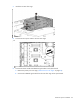
The server supports FBWC. FBWC consists of a cache module and a capacitor pack. The DDR cache module
buffers and stores data being written by the controller. When the system is powered on, the capacitor pack
fully charges in approximately 5 minutes. If a system power failure occurs, a fully charged capacitor pack
provides power for up to 80 seconds. During that interval, the controller transfers the cached data from DDR
memory to flash memory, where the data remains indefinitely or until a controller retrieves the data.
The data protection and the time limit also apply if a power outage occurs. When power is restored to the
system, an initialization process writes the preserved data to the storage drives.
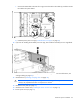
CAUTION: The cache module connector does not use the industry-standard DDR3 mini-DIMMs.
Do not use the controller with cache modules designed for other controller models, because the
controller can malfunction and you can lose data. Also, do not transfer this cache module to an
unsupported controller model, because you can lose data.
CAUTION: To prevent a server malfunction or damage to the equipment, do not add or remove
the capacitor pack while an array capacity expansion, RAID level migration, or stripe size
migration is in progress.
CAUTION: After the server is powered down, wait for 30 seconds, and then check the amber LED
before unplugging the cable from the cache module. If the amber LED flashes after 30 seconds,
do not remove the cable from the cache module. The cache module is backing up data. Data will
be lost if the cable is detached when the amber LED is still flashing.
IMPORTANT: The capacitor pack might have a low charge when installed. If the pack does have
low charge a POST error message appears when the server is powered up, indicating that the
capacitor pack is temporarily disabled. No action is necessary. The internal circuitry
automatically recharges the capacitors and enables the capacitor pack. This process might take
up to 4 hours. During this time, the cache module functions properly but without the performance
advantage of the capacitor pack.
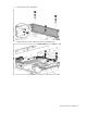
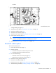
Storage controller installation guidelines
• Install the storage controller option in slots 1–3 of the primary PCI riser cage.
• Do not install a storage controller option in slot 4 of the primary PCI riser cage.
• The secondary PCI riser cage option supports storage controller installation.
• For more information on the riser board slot specifications, see "PCIe riser board slot definitions (on
page 12)."
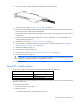
Installing a storage controller
HP recommends installing the storage controller option in a full-height expansion slot for better cable routing.
For more information about product features, specifications, options, configurations, and compatibility, see
the product QuickSpecs on the HP Product Bulletin website (http://www.hp.com/go/productbulletin).
IMPORTANT: For additional installation and configuration information, see the documentation
that ships with the option.