
Specifications


Removal and replacement procedures 42
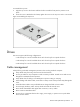
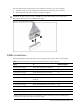
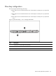
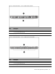
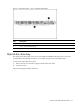
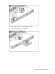
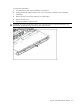
The next steps illustrate the removal of power cable from connector J51, 60, 64 and 82.
1. Squeeze on the top of the retaining latch attached to the cable end of the connector.
2. Grasp the cable end of the connector and pull it straight up.
CAUTION: Always pull the connector—NEVER pull on the cable. Pulling on the cable could
damage the cable and result in a failed power supply.
Figure 3 Unplugging Power Cable
Cable connections
The following tables provide information about switching power supply cable connector labels.
Table 8
Cable connections from the 460W/750W Hot-plug Power Supply (Optional)
Cable
To
Cable Designator
Switching power supply System board 24-pin power connector P1
Switching power supply System board 8-pin power connector P2
Switching power supply System board 4-pin power connector P3
Switching Power Supply Graph card power connector P4
Switching Power Supply 4/8 HDD hot-plug Backplane power
connector
P5
Switching power supply
Optical disc drive
CD
Switching Power Supply System board backplane power connector RPS
Switching power supply 2 HDD hot-plug Backplane power connector P10/P11
Switching power supply 4 Non hot-plug HDD P6,P7,P8,P9
NOTE: P6,P7,P8,P9,P10 and P11are extended connectors from P5, P4 are the extended 6-pin
connector from 10-pin P4 connector.of power supply.