
Specifications


Removal and replacement procedures 41
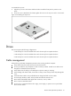
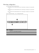
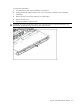
To reinstall the top cover:
1. Align the top cover to the chassis and then slide it towards the front panel to position it into
place.
2. Once the cover is attached to the chassis, tighten the screw on the top cover with a T-10 wrench.
Figure 2 Reinstalling the Top Cover
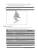
Drives
The server supports the following configurations:
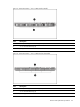
• 2 drive bays for 3.5-inch hard disk drives and 1 drive bay for an optical disc drive
• 4 drive bays for 3.5-inch hard disk drives and 1 drive bay for an optical disc drive.
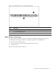
• 8 drive bays for 2.5-inch hard disk drives and 1 drive bay for an optical disc drive.
Cable management
Always follow good cable management practices when working inside the computer.
• Keep cables away from major heat sources like the heat sink.
• Do not jam cables on top of expansion cards or memory modules. Printed circuit cards are not
designed to withstand excessive pressure.
• Keep cables clear of sliding or moveable parts to prevent cutting or crimping.
• When folding a flat ribbon cable, never fold to a sharp crease. Sharp creases may damage the
wires.
• Some flat ribbon cables come pre-folded. Never change the folds on these cables.
• Do not sharply bend any cable. A sharp bend can break the internal wires.
• Never bend a SATA data cable tighter than a 30 mm (1.18 in.) radius.
• Never crease a SATA data cable.
• Do not rely on components like the drive cage, power supply, or system cover to push cables
down into the chassis.