
Specifications


Table Of Contents
- Product description
- External component identification
- Illustrated parts catalog
- Removal and replacement procedures
- Preliminary replacement requirements
- Component replacement procedures
- Service tag
- Computer feet
- Battery
- Switch cover and keyboard
- Memory module
- Optical drive
- Speakers
- WWAN module
- Palm rest
- Hard drive
- WLAN module
- Display assembly on computers with 15-in displays
- Top cover
- Power button board
- RTC battery
- Display assembly on computers with 14-in displays
- Bluetooth module
- Modem module
- USB connector assembly
- Heat sink and fan
- Processor
- System board
- SIM
- Computer Setup
- Specifications
- Computer specifications
- 14.1-in WXGA display specifications
- 15.6-in WXGA display specifications
- Hard drive specifications
- DVD-ROM Drive specifications
- DVD±RW Double-Layer Combo Drive specifications
- Blu-ray Disc ROM Drive with SuperMulti DVD±R/RW Double-Layer specifications
- System DMA specifications, Windows Vista and XP
- System interrupt specifications, Windows Vista
- System interrupt specifications, Windows XP
- System I/O address specifications, Windows Vista
- System I/O address specifications, Windows XP
- System memory map specifications, Windows Vista
- System memory map specifications, Windows XP
- Screw listing
- Torx T8M2.5×6.0 screw
- Torx T8M2.5×4.0 screw
- Phillips PM2.0×2.0 screw
- Phillips PM2.0×3.0 screw
- Phillips PM2.0×3.0 screw
- Phillips PM2.5×6.0 screw
- Phillips PM2.5×11.0 captive screw
- Phillips PM3.0×4.0 screw
- Phillips PM2.0×4.0 screw
- Phillips PM2.5×3.0 screw
- Phillips PM2.5×4.5 screw
- Phillips PM2.5×3.0 broadhead screw
- Phillips PM2.5×7.0 screw
- Phillips PM2.5×9.0 captive screw
- Phillips PM3.0×8.0 screw
- Backup and recovery
- Connector pin assignments
- Power cord set requirements
- Recycling
- Index
4. Remove the battery (see Battery on page 63).
5. Remove the following components:
a. Switch cover and keyboard (see
Switch cover and keyboard on page 64)
b. Optical drive (see
Optical drive on page 69)
c. Speakers (see
Speakers on page 73)
d. Palm rest (see
Palm rest on page 75)
e. Top cover (see
Top cover on page 90)
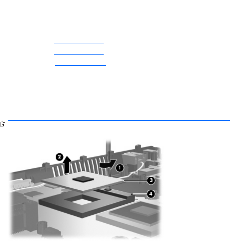
Remove the processor:
1. Position the computer right-side up with the front toward you.
2. Use a flat-bladed screwdriver to turn the processor locking screw (1) one-half turn counterclockwise
until you hear a click.
3. Lift the processor (2) straight up and remove it.
NOTE: When you install the processor, the gold triangle (3) on the processor must be aligned
with the triangle (4) embossed on the processor socket.
Reverse this procedure to install the processor.
Component replacement procedures 111