
Specifications


Table Of Contents
- Product description
- External component identification
- Illustrated parts catalog
- Removal and replacement procedures
- Preliminary replacement requirements
- Component replacement procedures
- Service tag
- Computer feet
- Battery
- Switch cover and keyboard
- Memory module
- Optical drive
- Speakers
- WWAN module
- Palm rest
- Hard drive
- WLAN module
- Display assembly on computers with 15-in displays
- Top cover
- Power button board
- RTC battery
- Display assembly on computers with 14-in displays
- Bluetooth module
- Modem module
- USB connector assembly
- Heat sink and fan
- Processor
- System board
- SIM
- Computer Setup
- Specifications
- Computer specifications
- 14.1-in WXGA display specifications
- 15.6-in WXGA display specifications
- Hard drive specifications
- DVD-ROM Drive specifications
- DVD±RW Double-Layer Combo Drive specifications
- Blu-ray Disc ROM Drive with SuperMulti DVD±R/RW Double-Layer specifications
- System DMA specifications, Windows Vista and XP
- System interrupt specifications, Windows Vista
- System interrupt specifications, Windows XP
- System I/O address specifications, Windows Vista
- System I/O address specifications, Windows XP
- System memory map specifications, Windows Vista
- System memory map specifications, Windows XP
- Screw listing
- Torx T8M2.5×6.0 screw
- Torx T8M2.5×4.0 screw
- Phillips PM2.0×2.0 screw
- Phillips PM2.0×3.0 screw
- Phillips PM2.0×3.0 screw
- Phillips PM2.5×6.0 screw
- Phillips PM2.5×11.0 captive screw
- Phillips PM3.0×4.0 screw
- Phillips PM2.0×4.0 screw
- Phillips PM2.5×3.0 screw
- Phillips PM2.5×4.5 screw
- Phillips PM2.5×3.0 broadhead screw
- Phillips PM2.5×7.0 screw
- Phillips PM2.5×9.0 captive screw
- Phillips PM3.0×8.0 screw
- Backup and recovery
- Connector pin assignments
- Power cord set requirements
- Recycling
- Index
e. Hard drive (see Hard drive on page 78)
f. Display assembly (see
Display assembly on computers with 15-in displays on page 84 or
Display assembly on computers with 14-in displays on page 97)
g. Top cover (see
Top cover on page 90)
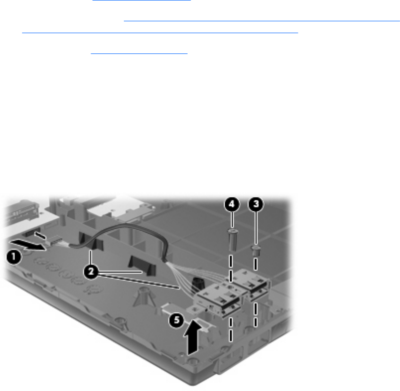
Remove the USB connector assembly:
1. Position the computer right-side up with the right side toward you.
2. Disconnect the cable from the system board (1) and remove the cable from the routing path in the
base enclosure (2).
3. Remove the Phillips PM2.5×3.0 screw (3) and the Phillips PM2.5×7.0 screw (4) that secure the
USB connector assembly to the base enclosure.
4. Remove the USB connector assembly (5) from the base enclosure.
Reverse this procedure to install the USB connector assembly.
Component replacement procedures 105